Week 8 - Challenge 1 - Draft Analysis on a Fan Cover
Project Title : DRAFT ANALYSIS OF A FAN COVER
OBJECTIVE :
The main objective of this challenge is to perform draft analysis on a fan cover by using CATIA V5R21 software which is given in the challenge. A report has to be prepared by explaining about what draft analysis and tooling axis and all the relevant images to the report.
DRAFT ANLYSIS :
Draft analysis is analysis which is performed on the objects in order to check the draft angle of various faces in a particular direction which is tooling direction.
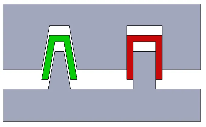
Every part like sheet metal parts which are generated from a Press Tool or some forming tools, may be the plastic parts which generally come out from the plastic moulds and maybe the casting parts, all such kind of parts required some draft face on the surfaces which are parallel to the tooling direction. If we don’t provide drafts on the surface then it will stick to the mould surface and whenever the mould is in motion, they will destroy the surface or also reduced the finishing surfaces.
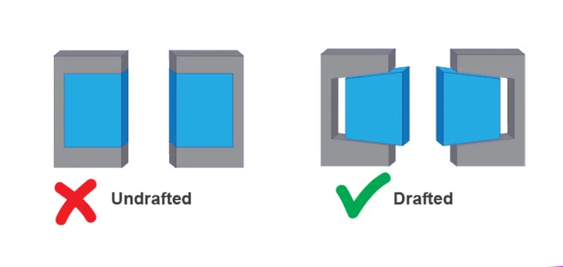
Draft is used for providing angles or tapers on product features such as walls, ribs, posts and bosses that lie parallel to the direction of release from the mold ease’s part ejection. Draft angles are designed in such way that they will assist depart rejection. By doing so we have a reduced cycle time and improved productivity. Draft value for a particular part is mostly decided by the material used for making it. Generally, for the plastic material draft value you are very from 0.5 degree to 3 degree.
A value of 3-degree draft for a plastic part is nominal and accepted all over the world.
TOOLING AXIS :
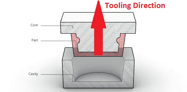
The Tooling direction is basically the direction that the mold pulls apart. The mold is built in two separate pieces, basically. You have a Cavity side and you have the Core side. The Core pulls apart from the Cavity and that’s the Dyeline or the Tooling Direction. And the axis which represents the tooling direction is called tooling axis and selection of this is axis is a crucial step while performing the draft analysis.
CREATION OF TOOLING AXIS :
The tooling axis is the major thing that has to be created before performing draft analysis. How a tooling axis has been created for this analysis is explained in the below steps.
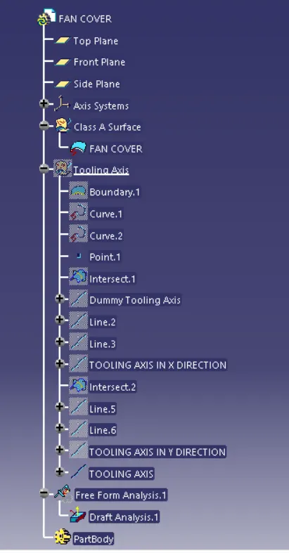
- Create an axis system and a point at the centre. The axis system should be similar to that of vehicle body axis system.
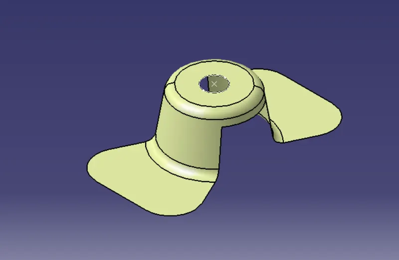
- By using intersection command on surface workbench create an intersection between ZX plane and the fan cover surface.
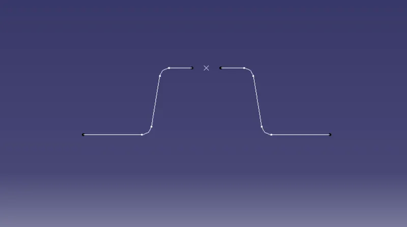
- Now create a dummy tooling axis by using point and direction which passes through the previously created point.
- Create line by using points on face which you think will create an issue. Make sure these points will clear the dummy tooling axis.
- Now create a line by using bisecting line command which is in line feature and select those two lines which are passing through the face. This bisecting command will create a mind-line between those two lines and name the bisecting line as tooling clearance line in X direction.
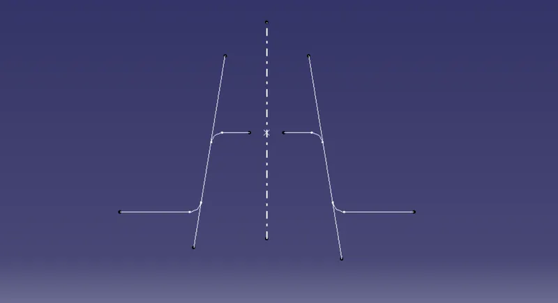
- Repeat the same steps in ZY plane fan cover and create tooling clearance line in Y direction and it will be like the image shown in below figure.
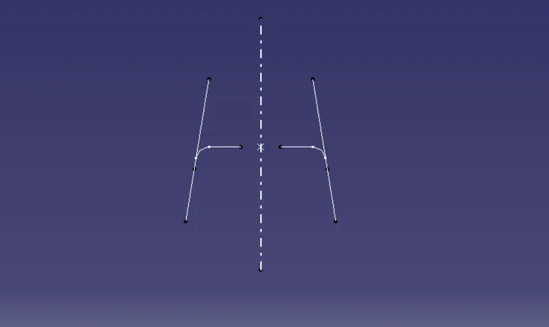
- By using tooling clearing line in X direction and tooling clearing line in Y direction create a line which is bisecting these lines. Name the new line as tooling axis.
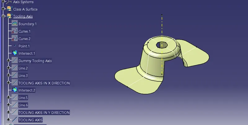
STEPS TO PERFORM DRAFT ANALYSIS :
- The first step in the draft analysis part is to check the given class A surface is joined properly or not. This can be done by observing the part visually by using join command.
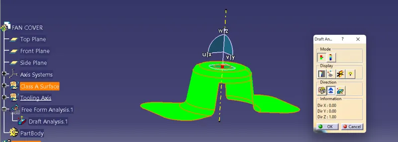
- From the image we can clearly observe that the surfaces are joined properly.
- The second step is to create a tooling axis the step to create tooling axis is explained very clearly.
- Go to insert>>Analysis>>Feature draft analysis.
- Make sure that in customize view parameters command in shading it has to be material.
- Now drag the red colored point on the compass to match the tooling axis which we have created.
- Click on the icon under the display command and a point will appear on your screen and tap the point on the surface of the fan cover.
- Change the angle from 2 degrees to 3 degrees on draft analysis. 2 dialogue box and on draft analysis dialogue box click ok.
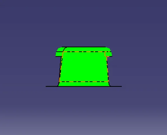
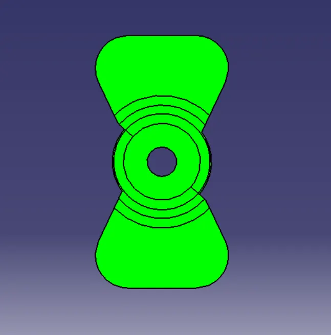
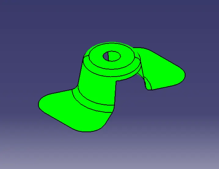
- Now go back to lock icon and click ok, and see how the object appearance. If it is in green colour we can say that the object is fine and we can proceed with that if it is showing in any other colour such as blue or red we have to modify our design.
PUBLICATIONS IN CATIA :
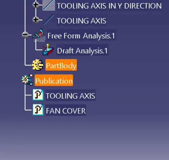
A publication acts as a reference to a geometric in CATIA V5. In 3DCS Variation Analysis CAA V5 Based, users can use published surfaces that copy the surface name, surface colour and other properties. Here in our draft analysis, we have published our tooling axis and fan cover.
Tree Structure :-
VIEWS OF FAN COVER AFTER DRAFT ANALYSIS :
- Front View
- Back View
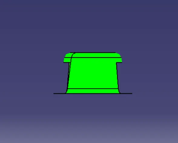
- Left View
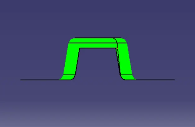
- Right View
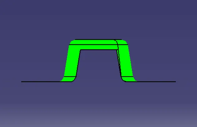
- Top View
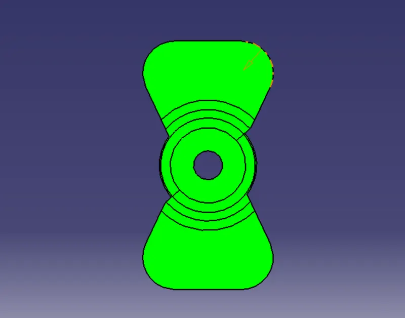
- Bottom View
- Isometric View
CONCLUSION :
And hence, Here I am concluding that the draft analysis on a fan cover has been performed successfully and the report has been prepared by attaching all the images which are required.