Week 8 - Challenge 1 - Draft Analysis on a Fan Cover
OBJECTIVE:
To perform the draft analysis on a fan cover by creating a tooling axis in CATIA software.
DRAFT ANGLE:
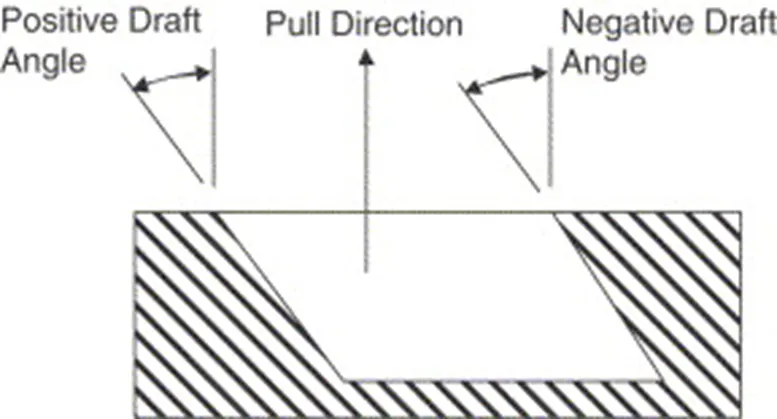
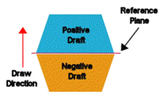
The tapered angle provided to the part along the tooling direction for manufacturing purpose is called draft angle.
NEED OF DRAFT ANGLE:
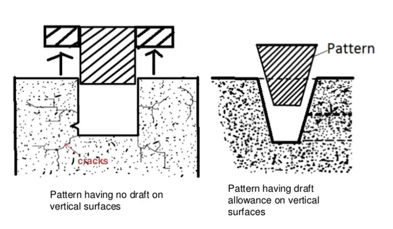
When the molten plastic material is cooled, it shrinks and gets tightly hold to the mold. Due to this, the ejection of the part is difficult. This may lead to the damage of the part and the mold. Preparing a new mold consumes more time and money. In order to avoid this, draft angle is given for the part.
DRAFT ANGLE RULES:
The draft angle is not the same for all components. It may vary based on factors like wall thickness, material selection, shrink rate, finish/texture and wall depth. The minimum draft angle is 0.5 degree to 1 degree. This angle is provided for holes and ribs. But, 3 degree is the nominal draft angle for most of the components.
DRAFT ANALYSIS:
The steps to be followed for performing draft analysis are given below.
Step 1: Check the boundary of the given component to make sure that there is no gap in between the class A surfaces.
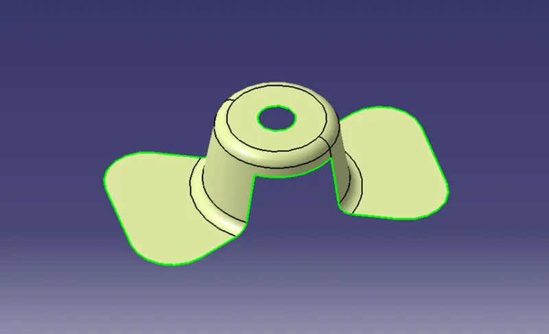
Step 2: Create a dummy tooling axis for our reference. Here it is along Z axis.
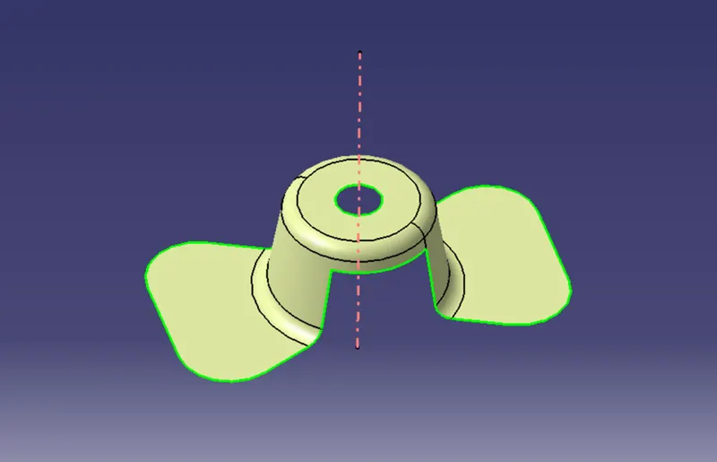
Step 3: Create an axis system or reference planes in the middle of the component.
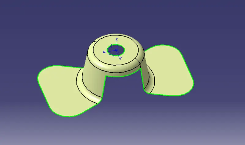
Step 4: Create an intersect between the ZX plane and the class A surface.
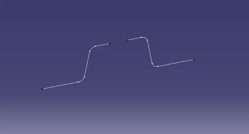
Step 5: Create reference lines with the intersect produced that are almost parallel to the dummy tooling axis. We can ignore the lines that are perpendicular to the axis.
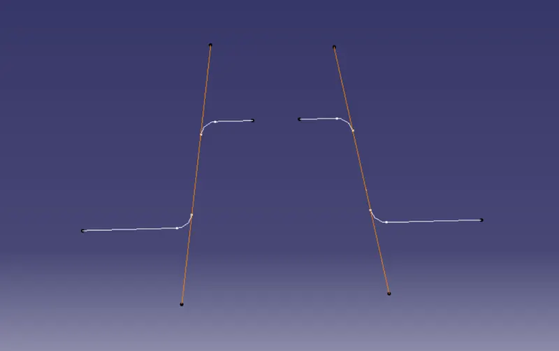
Step 6: Create a bisecting line for the reference lines created and this line denotes the tooling direction clearing along the X direction.
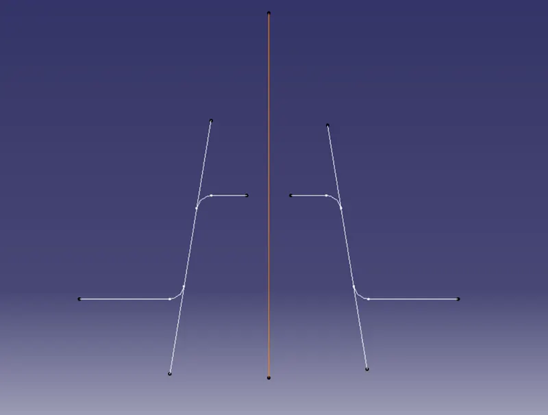
Step 7: Similarly, repeat step 4 to step 6 to create tooling direction clearing along the Y direction.
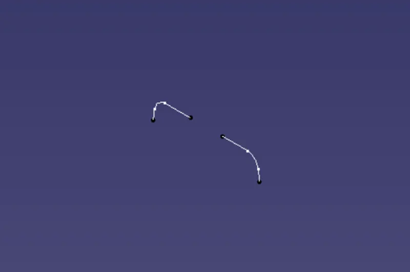
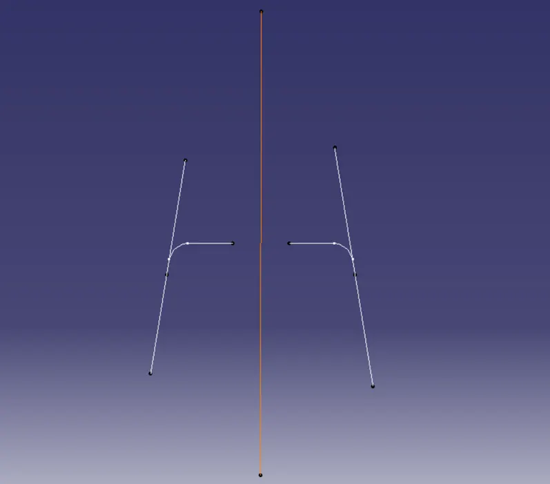
Step 8: Now, create a bisecting line for tooling direction clearing along X and Y directions. This is the final tooling direction.
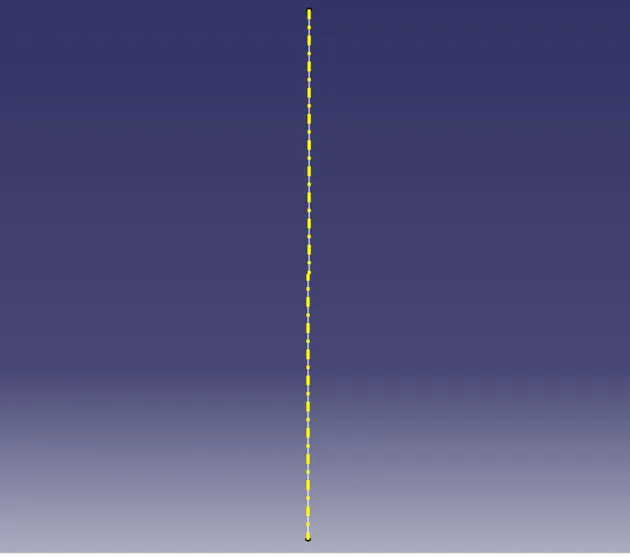
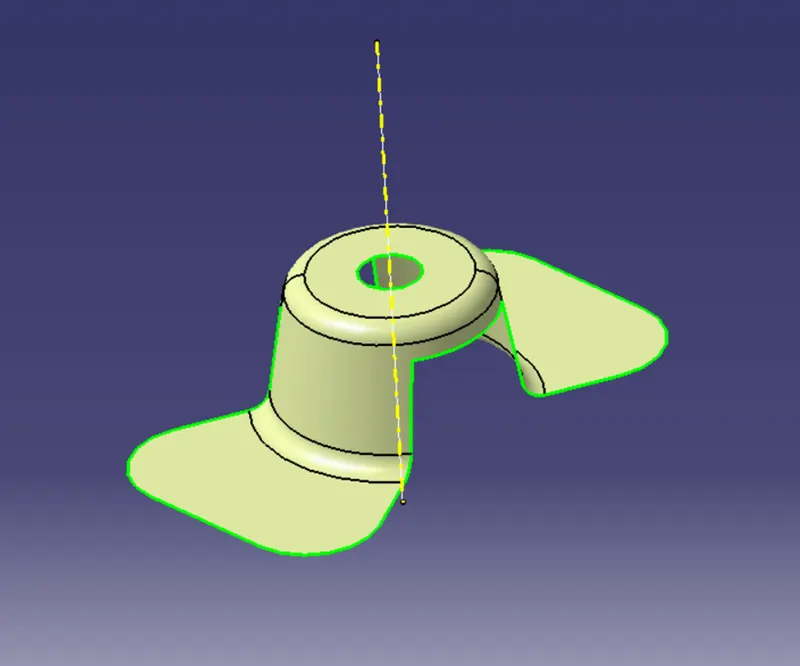
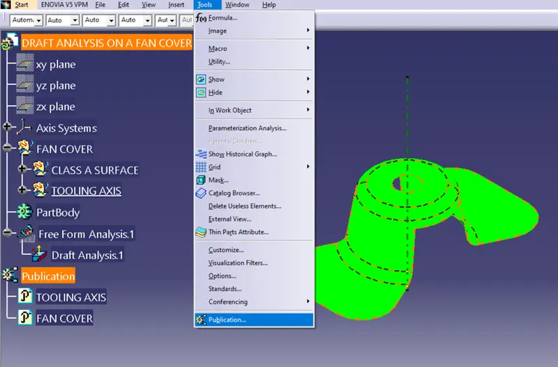
Step 9: Publish the class A surface and tooling direction for easy access.
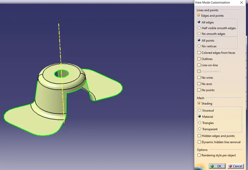
Step 10: Change the view to customized view and enable the material in shading option.
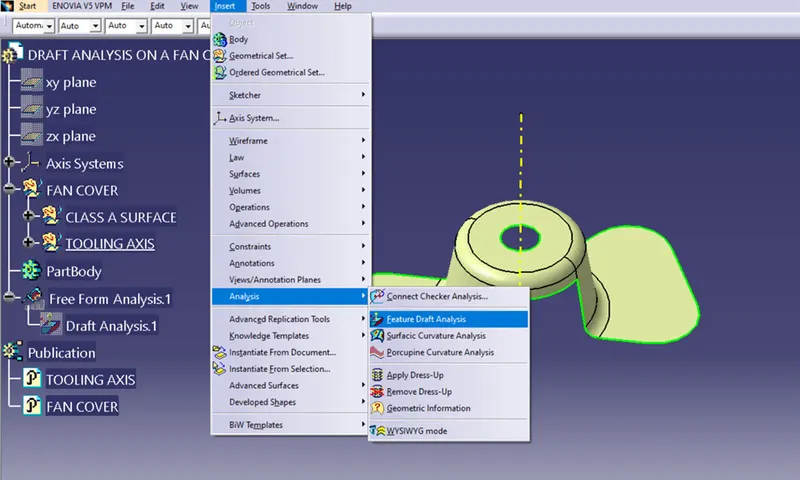
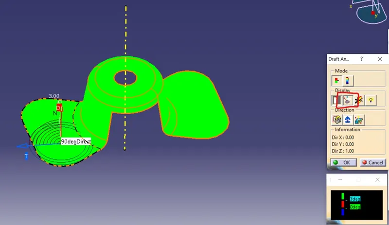
Step 11: Insert the feature draft analysis.
Step 12: Click the compass icon and place the compass along the tooling direction.
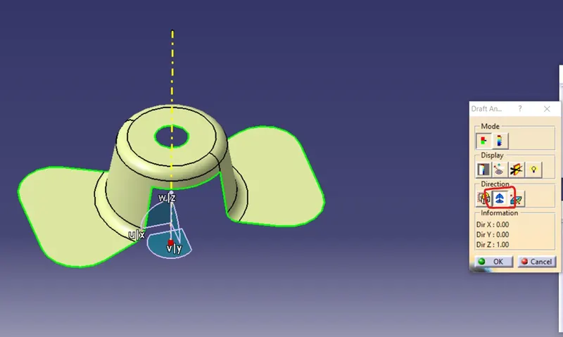
Step 13: Lock the draft direction and select the component to draft.
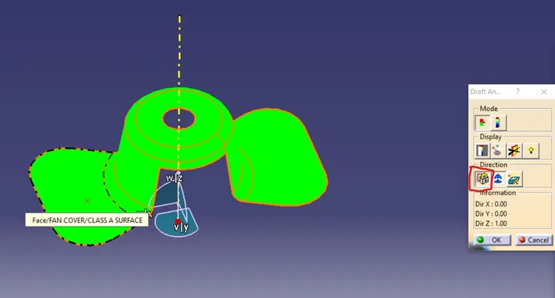
Step 14: Enable the color scale and change the draft value as required. Here 3 degree is given as draft angle.
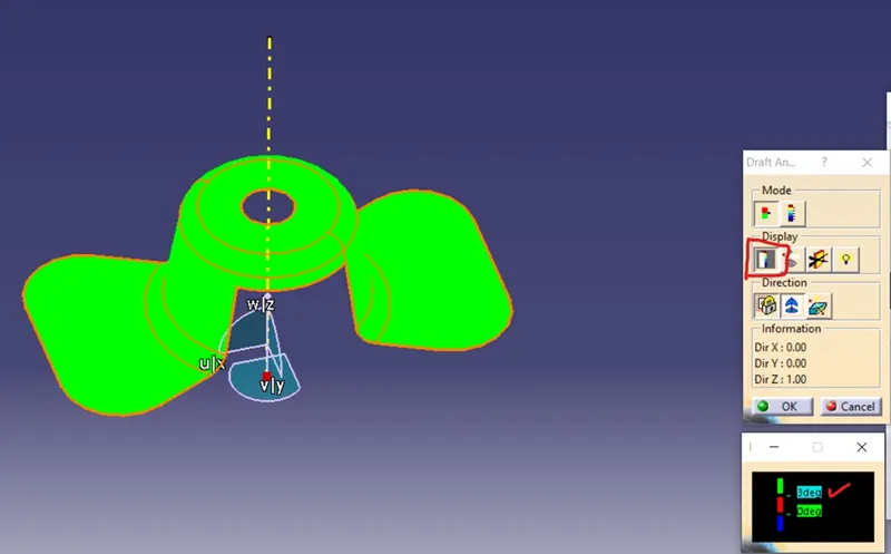
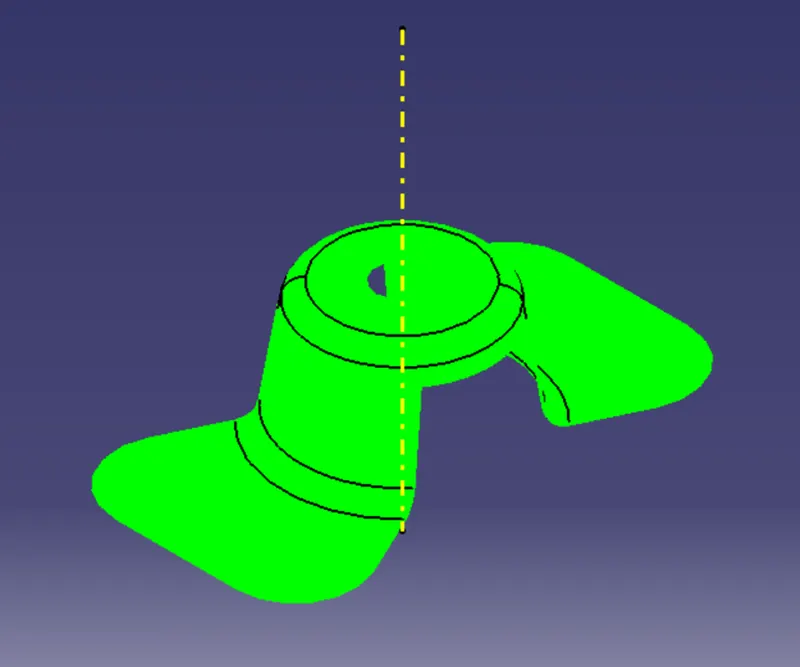
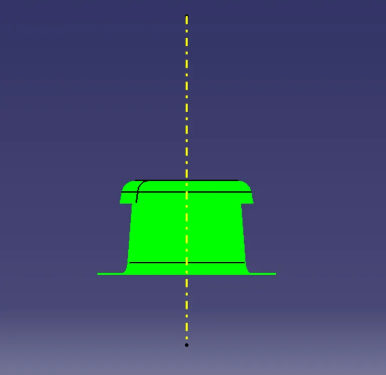
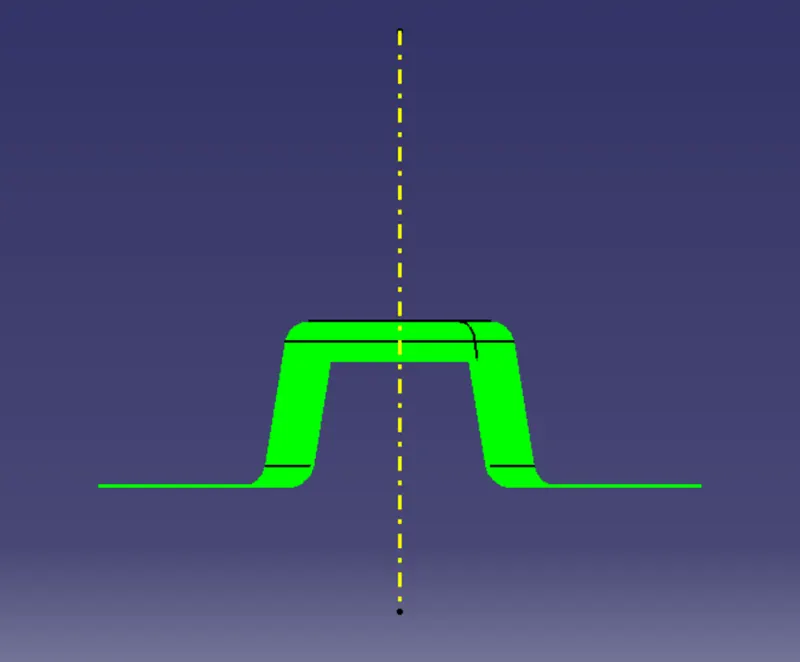
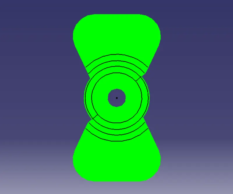
Step 15: The green color indicates that the surface is more than 3 degree from the tooling direction. The red color indicates that the surface is 0 to 3 degree from tooling direction. Blue color indicates that the surface is less than 0 degree from tooling direction which indicates the negative draft.
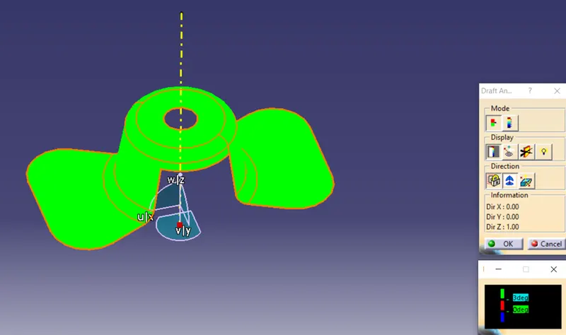
Step 16: In order to check the value of an individual surface, select the icon that analyses under the running point.
DRAFT ANALYSIS ON DIFFERENT VIEWS:
ISOMETRIC VIEW:
FRONT VIEW:
SIDE VIEW:
TOP VIEW:
CONCLUSION:
Thus a report is made on draft angle and also draft analysis is performed on the given fan cover by creating tooling axis.