Radar Mast & Final Assembly of Yacht
PROJECT REPORT
INTRODUCTION
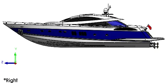
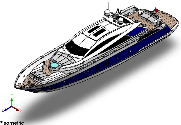
This project explains about the designing of different parts of Yacht and assembling them to get a complete model of the Yacht using Solidworks. It also tells about the rendering of the model using Solidworks Visualize to make the Yacht more natural and realistic.
MODELLING & ASSEMBLING FEATURES
The various modelling features used for modelling the Yacht are discussed as follows:
- EXTRUDE:
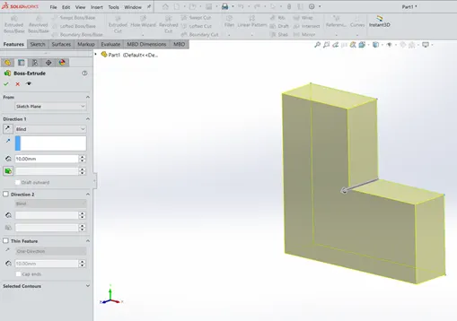
It is a basic tool in Solidworks which converts a 2D sketch in to a 3D model with respect to its geometry in normal direction. First we have to draw a fully closed 2D sketch and then extrude it by defining its starting point, ending point, contours and direction of extrusion.
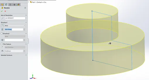
- REVOLVE:
The revolve feature is used to revolve a 2D sketch along an axis or centerline and makes it a 3D model. A 2D sketch is drawn and revolved by selecting a line as a reference for axis of rotation and defining the angle of rotation.
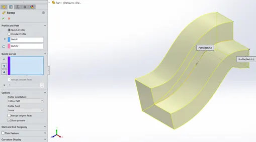
- SWEEP:
A sweep tool is used to sweep a closed 2D sketch along an open or closed path. This tool is generally used for making tubes and bars. A closed loop and a path to sweep are required.
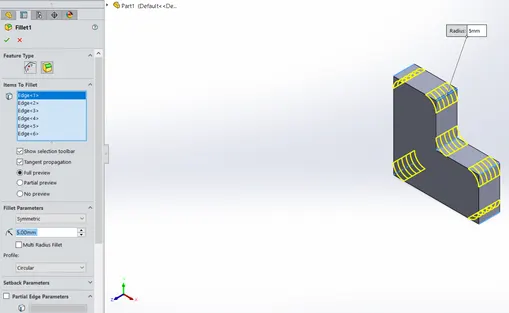
- FILLET:
A fillet is a tool used to round an edge, vertex or face on both inside and outside of a 2D or 3D model. The fillet type, location and radius of the fillet are defined.
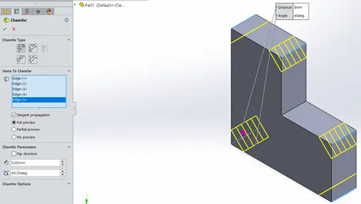
- CHAMFER:
A chamfer is used to remove a sharp edge by creating a sloped edge, vertex or face. Distance and angle of the chamfer are defined.
- MIRROR:
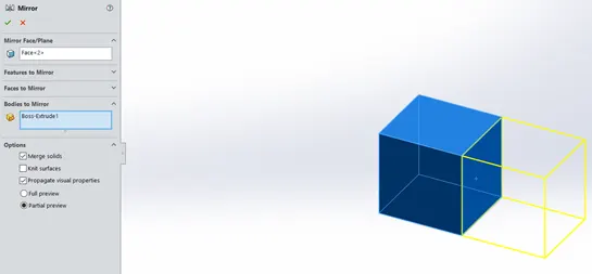
Mirror tool in Solidworks is used to copy a 2D or 3D object about a reference line or plane. We can have either only the mirrored object or both the original and mirrored objects.
- SHELL:
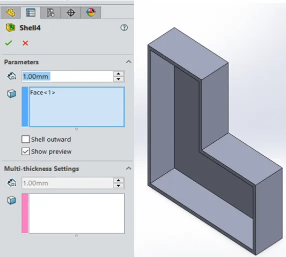
The shell tool hollows out a part, leaves open the faces you select, and creates thin-walled features on the remaining faces. If you do not select any face on the model, you can shell a solid part, creating a closed, hollow model. You can also shell a model using multiple thicknesses. The thickness of the shell is defined.
- LINEAR & CIRCULAR PATTERN:
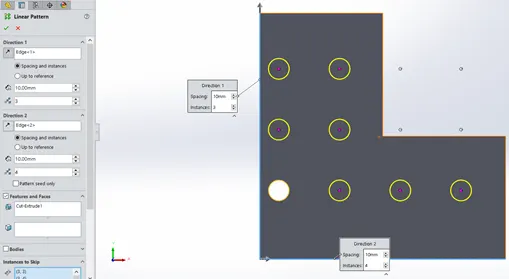
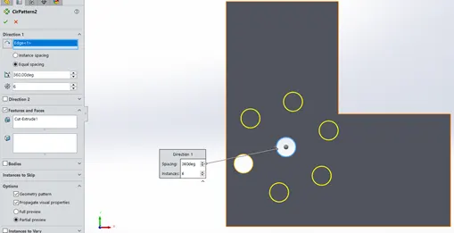
The Linear Pattern Command is used to drive features, faces, or bodies in a linear direction. The Circular Pattern Command is an excellent tool used to replicate features, faces, or bodies in a rotational manner about an axis.
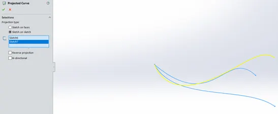
- PROJECTED CURVES:
A projected curve is a 3D curve that represents the intersection of two extruded surfaces of two sketches on intersecting planes.
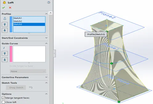
- LOFT:
Loft is a feature used for making transitions between different profiles on different planes. First, we have to create different planes and draw different sketches on them. Then click on loft tool and select the above sketches. We can adjust the twist of the solid body by moving the green balls as shown in the figure.
NOTE: The above mentioned tools are some of the features used to create a solid body. The following tools have been used to create surfaces using lines, curves and splines.
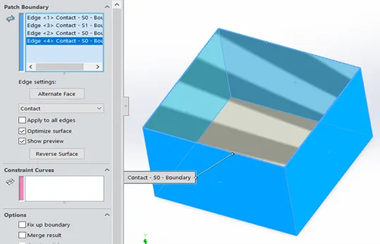
- FILLED SURFACES:
Filled surface is a feature in Solidworks used to close or seal an opened part. We can do this by clicking on the filled surface tool and selecting the sketches or edges of the surfaces or both.
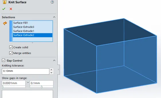
- KNIT SURFACE:
Knit surface is a tool for combining two or surfaces into one. We can also merge them, control gap between them and also create a solid body if the surfaces are closed. The surfaces have blue edges before knitting. But when knitted, they turn to black edges.
- RULED SURFACE:
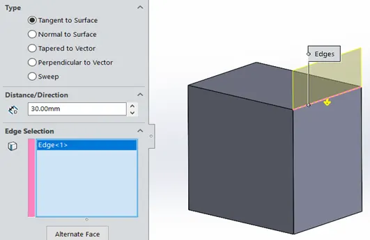
This tool is used to create an individual surface that is normal or tangent to a specified edge or surface. There are five different types of ruled surfaces. While using this tool, we have to select the edge or surface and select the type and direction of the ruled surface.
- TRIM SURFACE:
This tool is used to remove the unwanted surface from a required surface or body. We should select a surface as trim tool and then select the unwanted surface to be removed. These two surfaces should intersect each other.
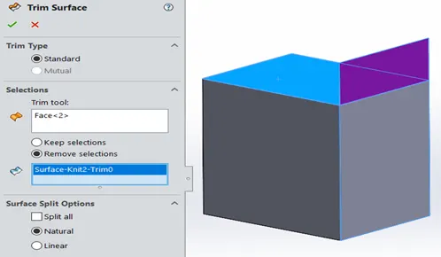
Similarly, we also have extrude, revolve, sweep, loft, etc tools for surfaces.
- MATES:
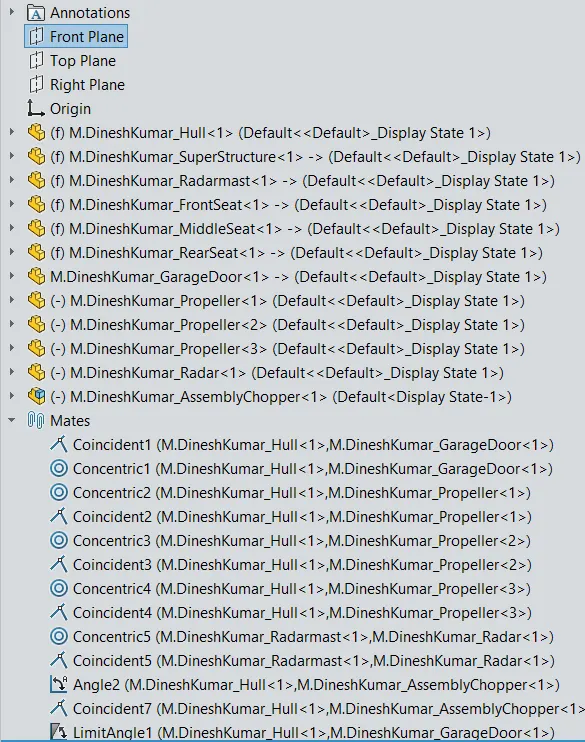
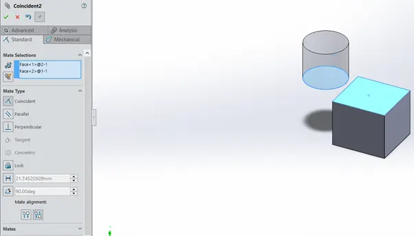
Mate operation is the basic tool for assembling the parts. There are various mate operations such as coincident, parallel, perpendicular, tangent, concentric, lock, etc. We can mate two faces by defining distance or angle between them.
DESIGNING APPROACH:
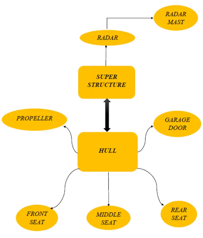
MODELLING
- PROPELLER:
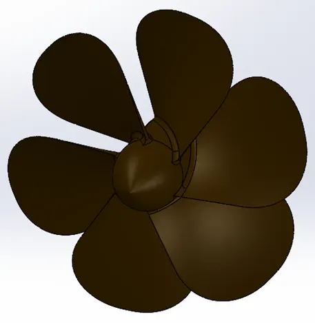
Propeller is a kind of rotor used to move the Yacht forward or backward by changing the rotation of blades. They are rotated by the power transmitted from engine. The hub was created initially, by using splines and revolve feature. Then the blades were created using loft and circular pattern features. Finally, appearance was given to it.
- RADAR:
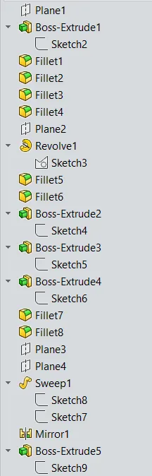
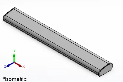
Radar is used for navigation of ship in sea and to detect other ships and obstacles around the ship to avoid collision with them by using radio waves. This part was created by drawing some sketches and using features like extrude, fillet and mirror.
- HULL:
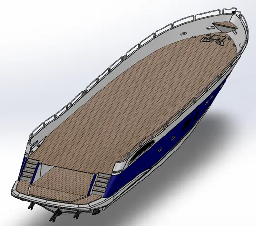
The hull is the base of the ship. The bottom part of the hull lies in the water, whereas the upper part lies on top of the water. The bottom part contains the engine and propeller of the ship. The upper part contains the seats and superstructure. This hull is used for floating above water by resisting forces and also supports the weight of all other parts. This hull was difficult to create. Blueprints were used to create this. The bottom of hull was created by drawing lines, curves and splines, and then surface features like extrude, loft and filled surfaces have been used. A space for garage was created by using extrude cut. Stairs and propeller shafts were created and grills were designed by using sweep feature. Then fillets and chamfers were applied to the required parts. And then decals were added to the deck surface and stairs.
- GARAGE DOOR:
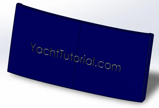
Garage is used to contain vehicles like car or bike. A reference for garage door was saved while creating hull. Using this reference, the door for garage was modelled and text were added on this door.
- FRONT, MIDDLE AND REAR SEATS:
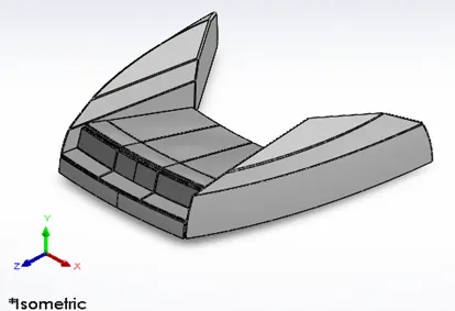
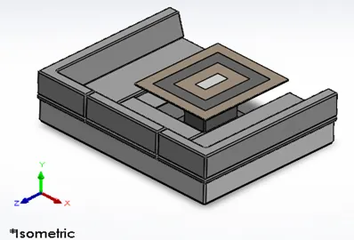
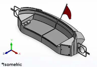
Seats are used to sit and relax during the journey. Here, the seats are located open space to enjoy view of sea. Seats are located in front, middle and rear of the Yacht. A surface was created on the deck while creating the hull. Using this deck surface and blueprints as references, the seats were modelled. These were modelled by using features like surface sweep, fill surface, extrude cut. 3D sketches were drawn to model a flag at the rear seat and surface loft feature was used. Finally, appearance was given to the seats.
- SUPERSTRUCTURE:
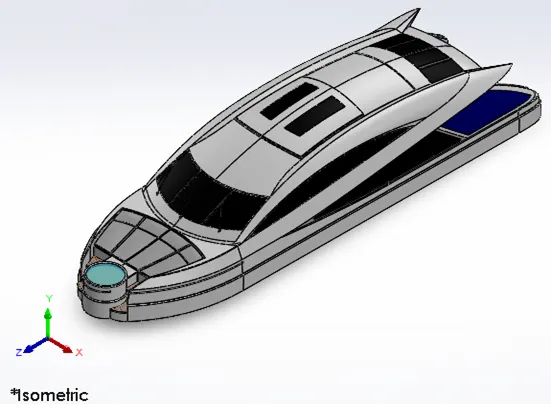
Superstructure is the part above the hull. It consists of the cabin that has control unit for sailing the ship. The bottom face of this part touches the deck surface of the hull. The radar and radarmast are placed on the top of the superstructure. So, the deck surface created in hull and blueprints were used as the references for this superstructure. The base of this part was modelled by drawing lines, curves and splines and using surface features like extrude, loft, fill and knit surfaces. Other parts were modelled by using extrude, extrude cut, mirror, fillet and chamfer. Then appearances were applied to the windows, doors and superstructure. This part was difficult to model.
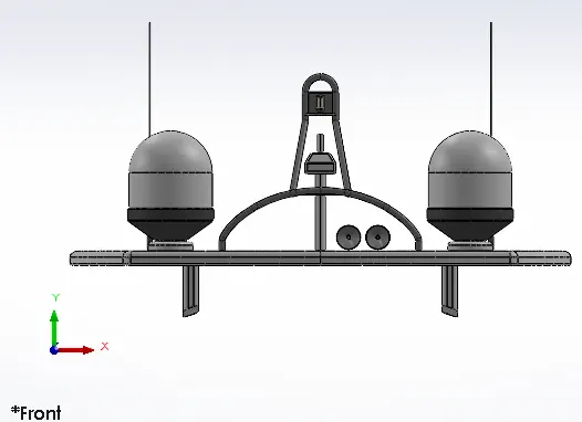
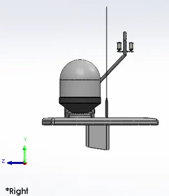
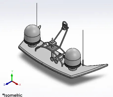
- RADAR MAST:
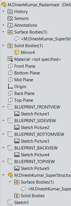
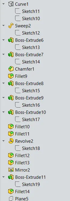
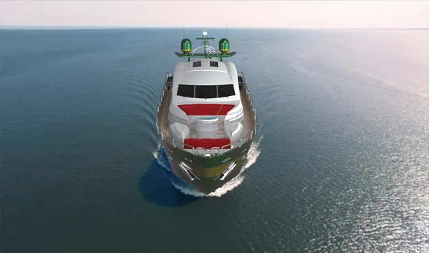
The radar mast is a structure that consists of antenna, horns, lights and radar and provides support for them. It is used to detect other ships and obstacles to avoid collision. It is used for safety and navigation purpose. A reference surface was created for radar mast while modelling the superstructure. Using this surface and blueprint as references, radar mast was modelled. This was easy to model. Initially surfaces were created and then solid bodies were created.
ASSEMBLY OF THE YACHT
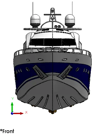
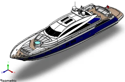
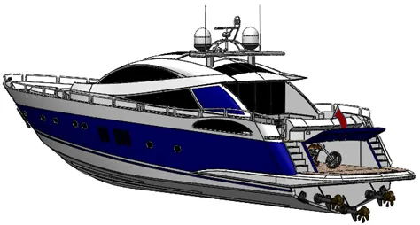
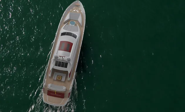
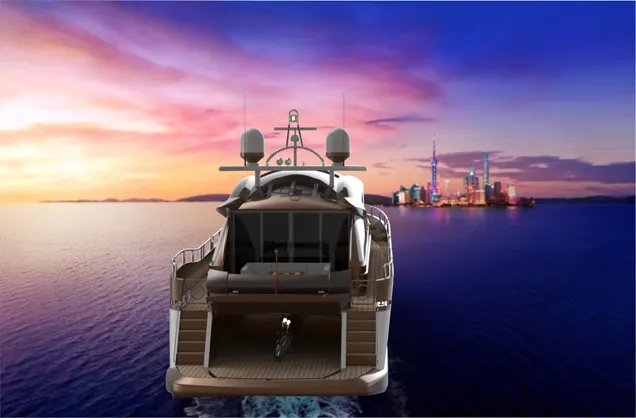
First, the hull was imported and automatically fixed. Then superstructure, seats and radar mast were imported. As reference surfaces were used to create these parts, they were automatically fixed. Then garage door, propeller and radar were imported and mated with the particular parts. Chopper was also imported and placed inside the garage to make it more real and attractive.
RENDERING OF THE YACHT
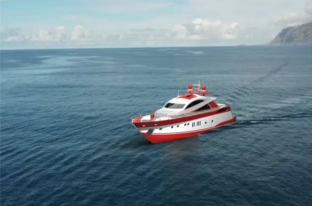
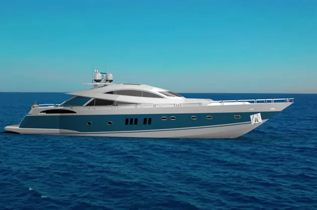
In rendering, the Yacht was made to set up in such a way to look natural and unique. Decals were added to the body parts. Views and light directions were changed. Using Solidworks Visualize, the appearances, background scenes and camera views were changed. Then final rendering was done to make the Yacht, a cool and realistic one.
Google drive link for render and report files:
https://drive.google.com/drive/folders/1_-OfsqTiMxIm-MW6R1TKHN5hWOdG6nIF?usp=sharing