Week 8 - Challenge 1 - Draft Analysis on a Fan Cover
Challenge 1 - Draft Analysis on a Fan Cover:
OBJECTIVE:
Create the tooling axis for the given Fan cover model meeting the requirements of the draft angle and perform the Draft analysis on the model.
TOOL:
CATIA V5
SO, WHAT IS DRAFT ANALYSIS FIRST OF ALL?
Draft analysis is a method of checking the draft angle on various faces of a part with a particular direction.
AND WHY DRAFT IS IMPORTANT?
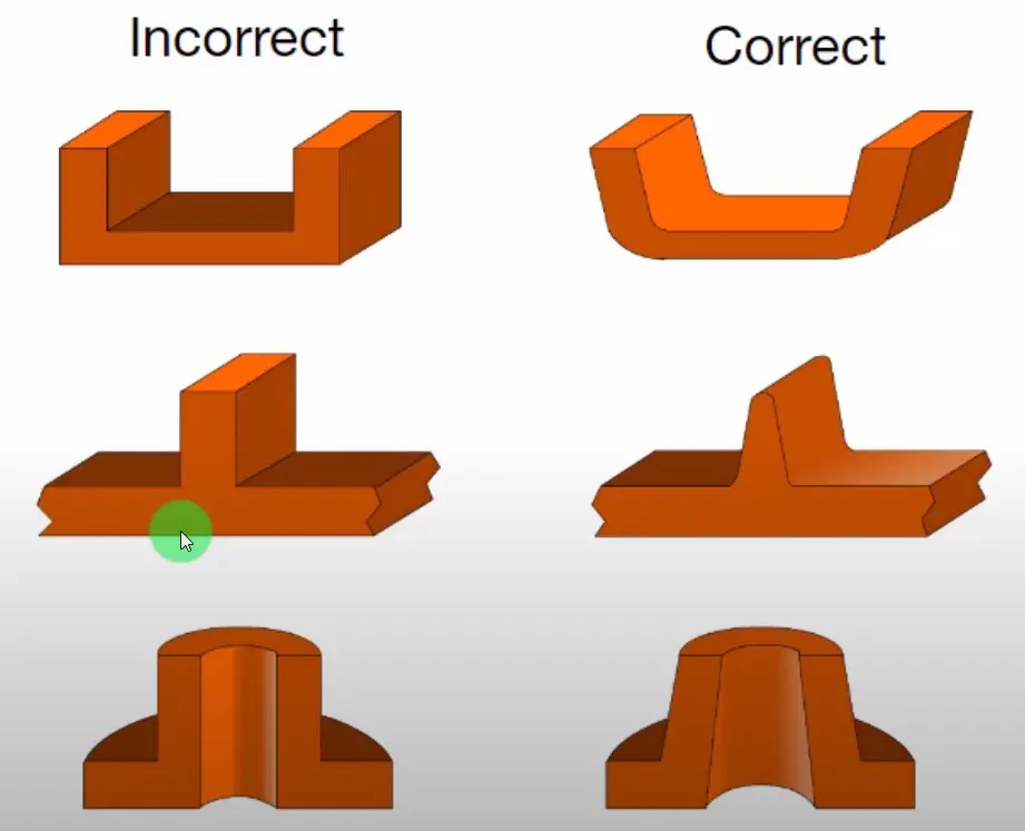
When developing parts for plastic injection molding, applying draft (or a taper) to the faces of the part is critical to improving the moldability of your part. Without it, parts run the risk of poor cosmetic finishes, and may bend, break, or warp due to molding stresses caused by the plastic cooling.
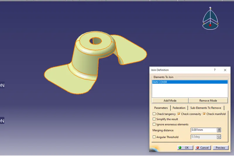
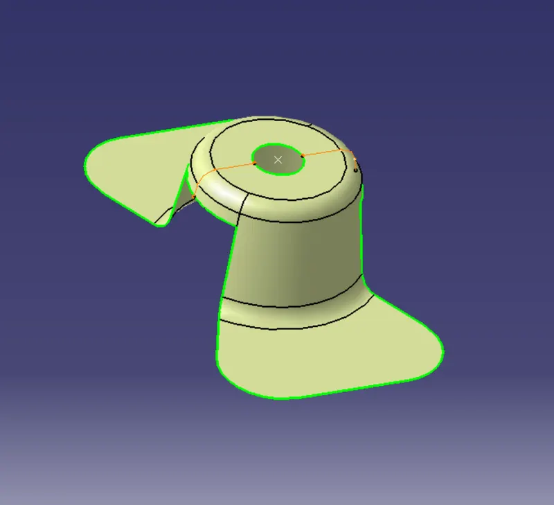
Here we've got a cat part
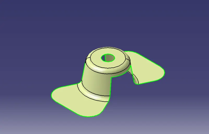
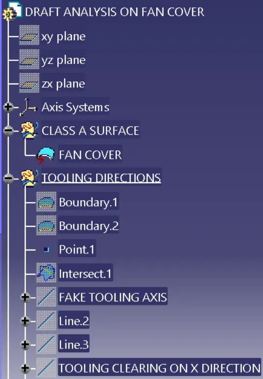
And for essential thing we gotta make sure that there's no gaps on the surface of part
then taking a boundry of itself
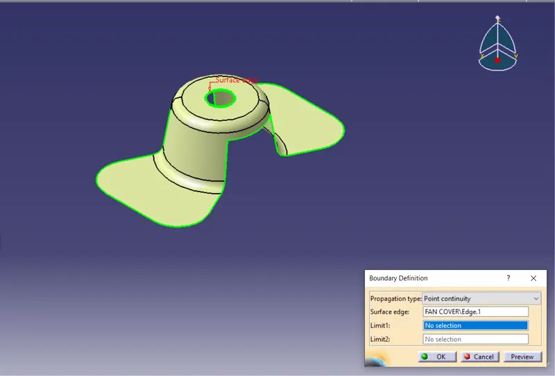
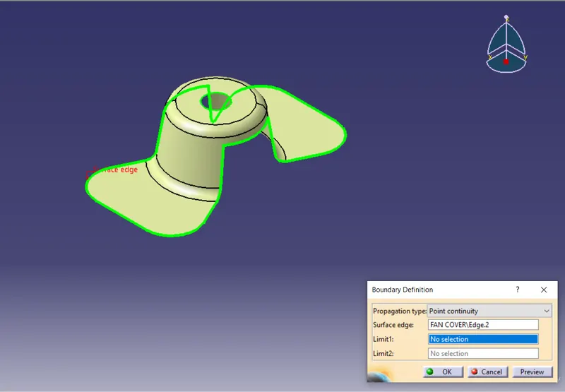
Then i created a point over the circle and take a inersection on x direction
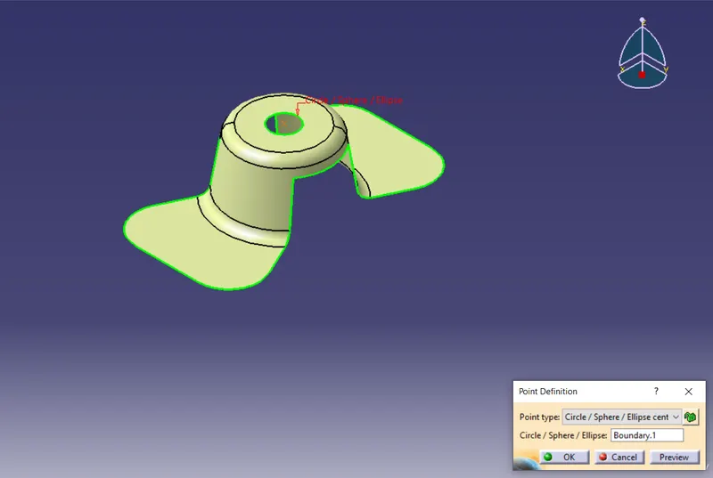
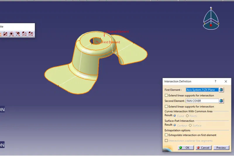
then i created a fake tooling axis for a refference
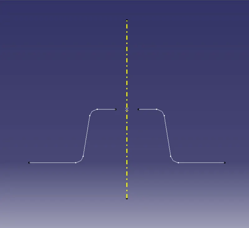
then i created lines on a both side of the intersection curves
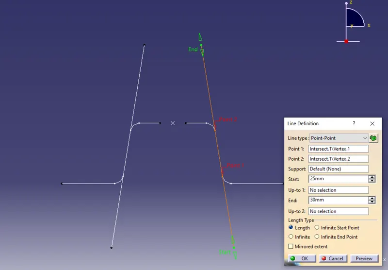
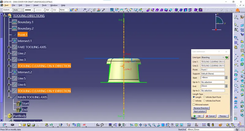
then i created a tooling clearing for x direction with bisecting line tool
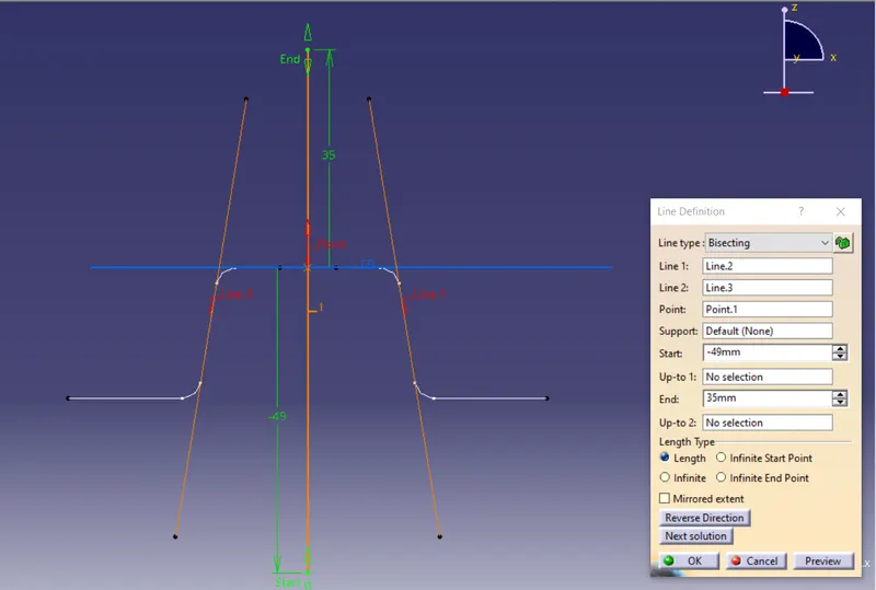
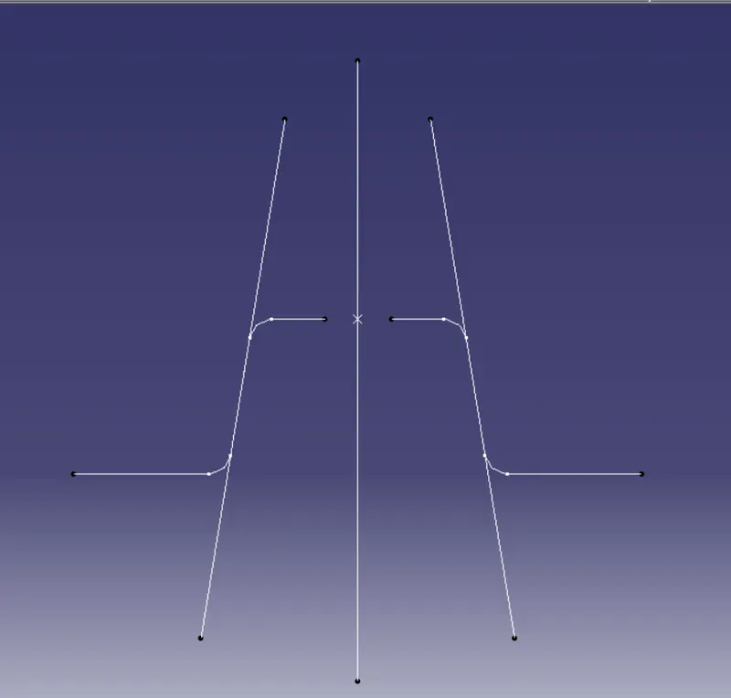
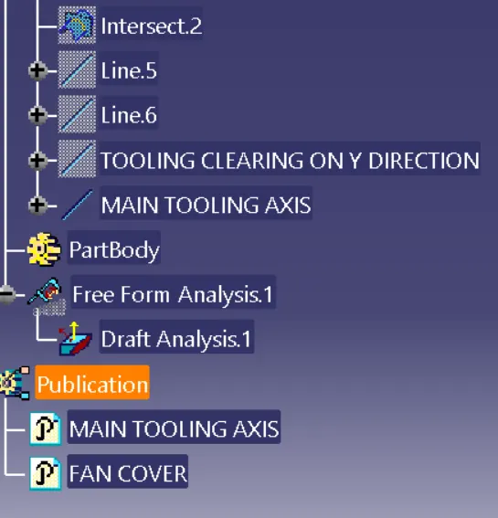
then i 've created a intersection curve on Y direction inorder to get a tooling clearing for Y direction
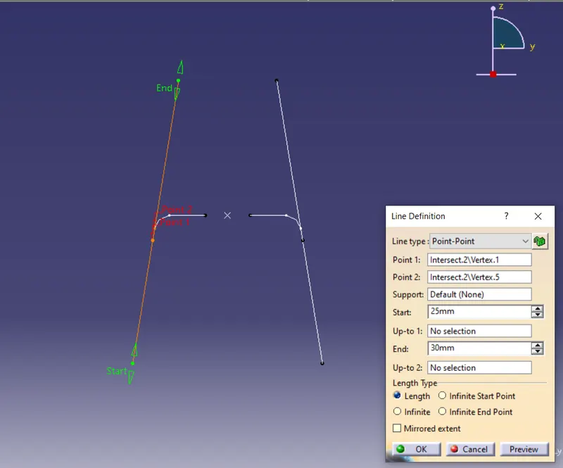
then i created lines on both ends of the intersection curves
Then i created line as a tooling clearing on Y direction
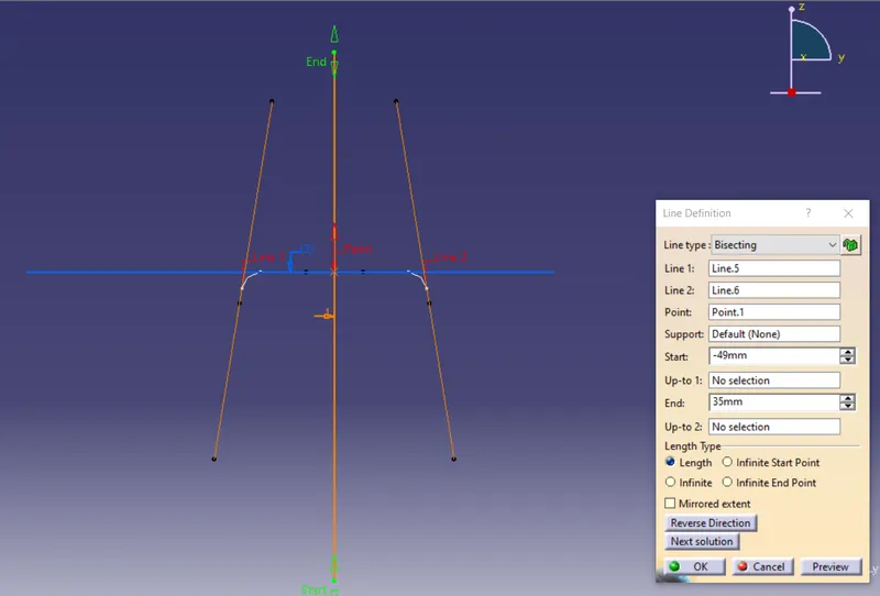
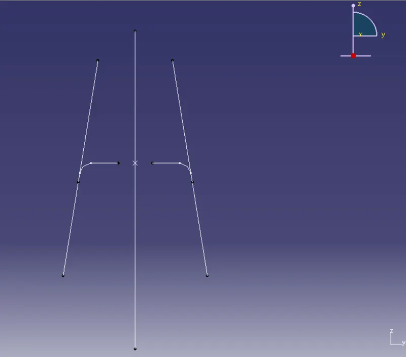
And eventually i created a main tooling axis by creating a bisecting line between tooling clearing X and Y
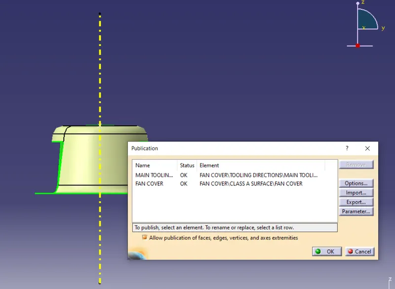
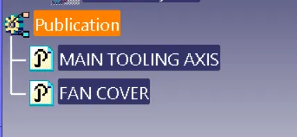
then i published tooling axis and fancover (class-A surface) as it's mentioned in challenge publishing the tooling direction and class a does help to find them easily for go further to creatre a class-B or thicksurface
Draft analysing:
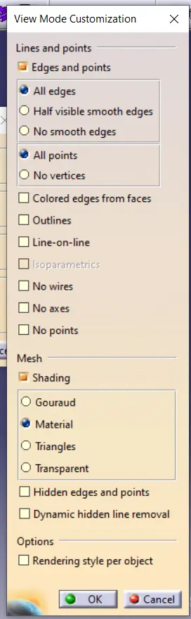
Before we do draft analysis we have to go for a customise the view mode and there will be a option called material
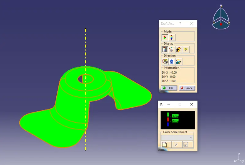
After we click a draft analysis tool it will appear on screen then it will give some info of color coding mode and direction and we have to click the option define a compass
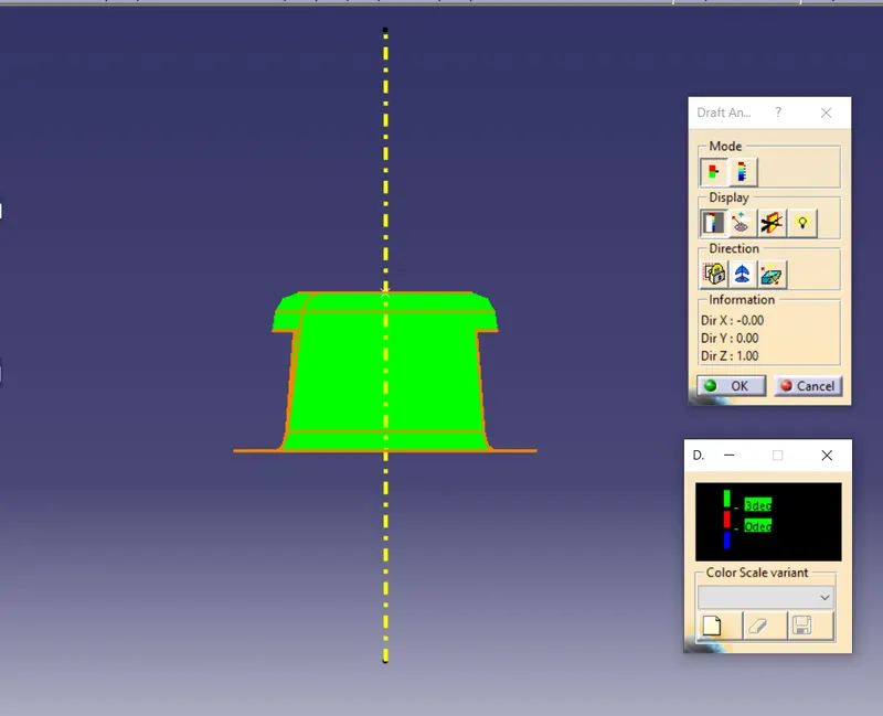
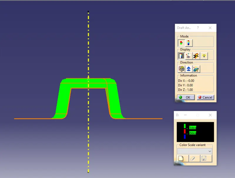
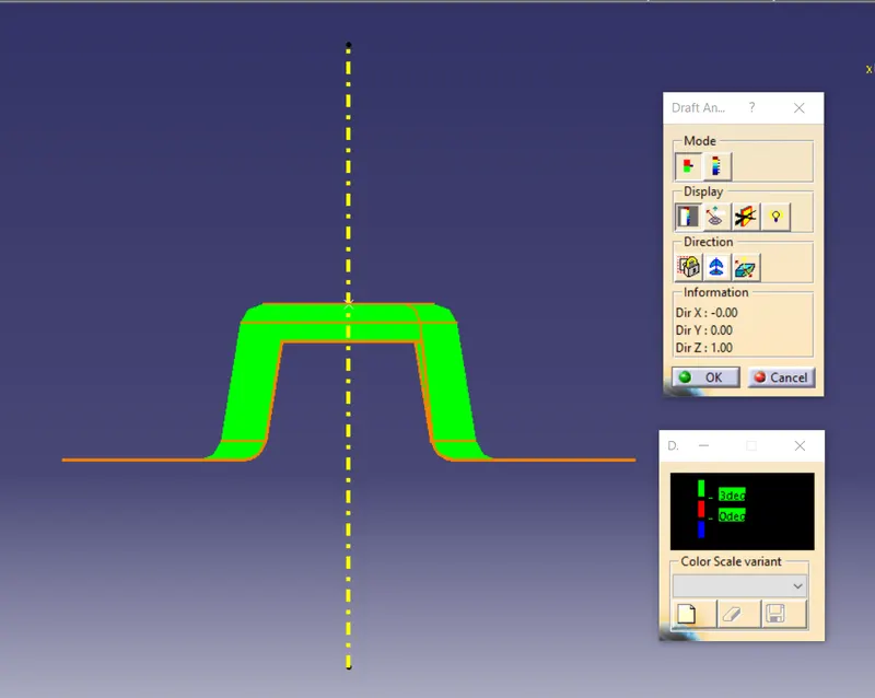
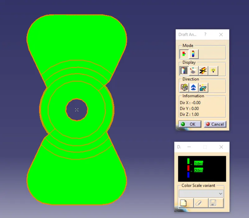
Then we have to lock the view by the tool lock or unlock the draft direction after that we have to click on a surface, now it remaining in green color on overall of itself with more than 3 degrees of draft angle it can easily get ejected from the mold
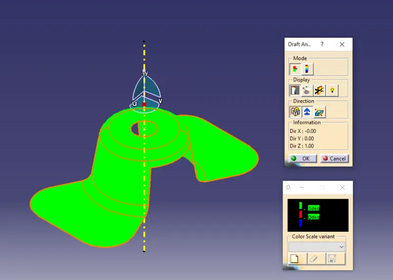
and there is an option called display it does can be use for hide or show the color scale varient box
and there's another option in display column which is analysis under the running point by this tool we can measure the angle respect to the tooling direction from any where on the surface of the part
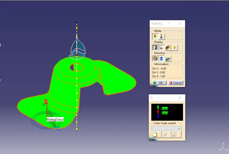
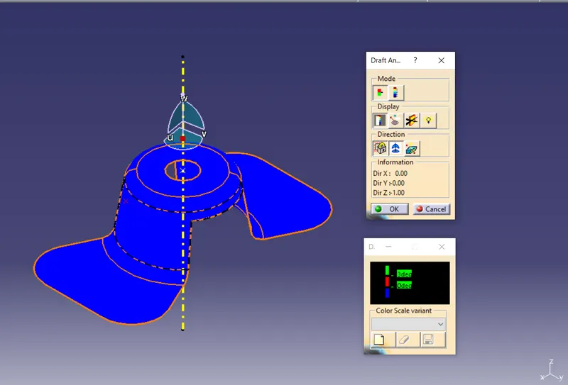
then we can invert the side of the part
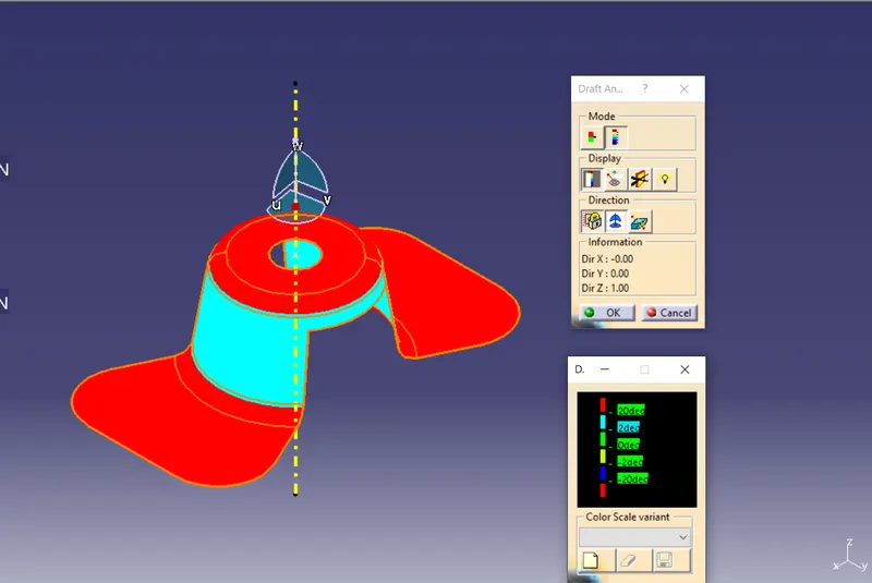
draft analysis results of below image
GEOMETRICAL TREE STRUCTURE:
FRONT VIEW:
LEFT VIEW:
RIGHT VIEW:
TOP VIEW:
ISO-METRIC VIEW: