Week 8 - Challenge 1 - Draft Analysis on a Fan Cover
AIM: To perform draft analysis of the given fan cover using bisection method
TOOLING AXIS :
it is the direction in which the tool enters the workpiece The default direction is Vertical, which is used for standard 3-axis machining. However, it can also be a fixed angle or a continuously changing orientation.
- Vertical — When selected, the tool remains aligned with the Z-axis of the active workplace. This is the default value and is the value used for standard 3-axis machining.
- Lead/Lean — When selected, the tool is at a fixed angle relative to the Z-axis of the active workplace. The tool is still dropped down the Z-axis onto the model.
- Lead — Enter the tool angle, relative to Z, in the feed rate direction (the direction of travel).
- Lean — Enter the tool angle, relative to Z, perpendicular to the feed rate direction (the direction of travel).
- Towards point — The tooltip tries to point towards the fixed point. The angle of the tool constantly changes. The head of the machine tool moves significantly, while the tip of the tool remains relatively still. This option orientates the tip of the tool towards a point.
draft analysis
- The Draft Analysis command enables the user to detect if the part that the user drafted will be easily removed.
- This type of analysis is performed based on color ranges identifying zones on the analyzed element where the deviation from the draft direction at any point, corresponds to specified values.
procedure:
- first, check whether there are any cracks/disjoints on the class A surface if there are fix them
- check all the surfaces, and select the surface about which the tooling axis is preferred
- once the tooling axis is created we have to create a dummy axis, for that create an axis, and select the corresponding surface and the axis (z-x) to get intersection lines
- then from those intersection lines select parallel lines
- create new lines using the point-point feature on the parallel lines ( do this for both parallel lines)
- select both new lines and select the bisect option to create a new line with direction and rename it as tooling direction x-axis
- do the same process for the x-y surface and create a new line and rename it as tooling direction y-axis
- select both zy and xz tooling direction line and create a bisecting line rename this line as tooling direction
- Click on the publication option and publish the line
procedure for draft analysis
- first, check if the model is in material mode
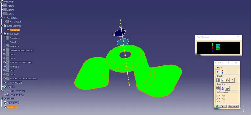
- then click on analysis and select feature draft analysis
- select the compass and align it with the tooling axis created before
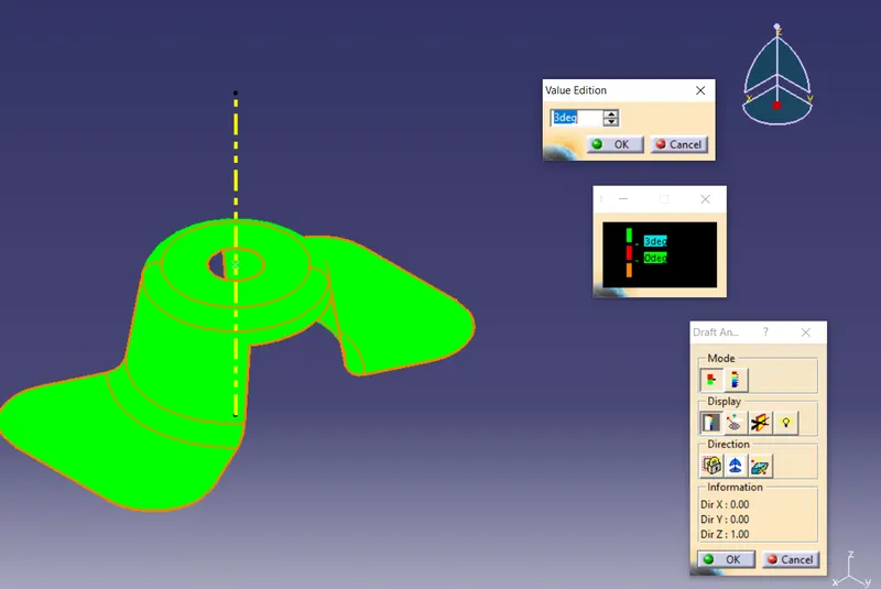
- now green color will appear on the model which signifies that it can be made under the given draft angle
- we can change the draft angle in the color tab by double-clicking it .. optimum draft angle is 3degree
screenshots
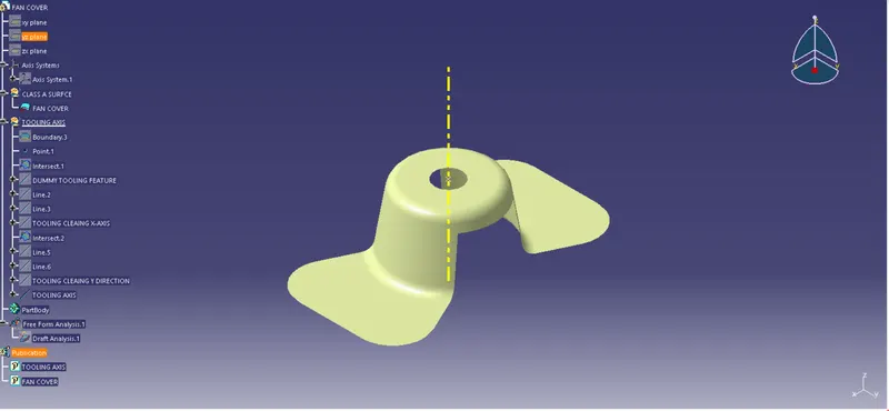
class a surface
draft