Week 8 - Challenge 1 - Draft Analysis on a Fan Cover
Aim:Creating the tooling axis for the given Fan cover model meeting the requirements of the draft angle and perform the Draft analysis on the mode
Introduction
Draft analysis is a method of checking the draft angle on various faces of a part with a particular direction.Providing angles or tapers on product features such as walls,the mold eases part ejection.
Rules of thumb for designing draft include:
• Draft all surfaces parallel to the direction of steel separation;
• Angle walls and other features that are formed in both mold halves
to facilitate ejection and maintain uniform wall thickness
• Use the standard one degree of draft plus one additional degree
of draft for every 0.001 inch of texture depth
• Use a draft angle of at least one-half degree for most materials.
Design permitting, use one degree of draft for easy part ejection.
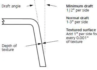
Procedure for Draft analysis:
First check the continuity of the class A surface boundary or Join Command
Boundary
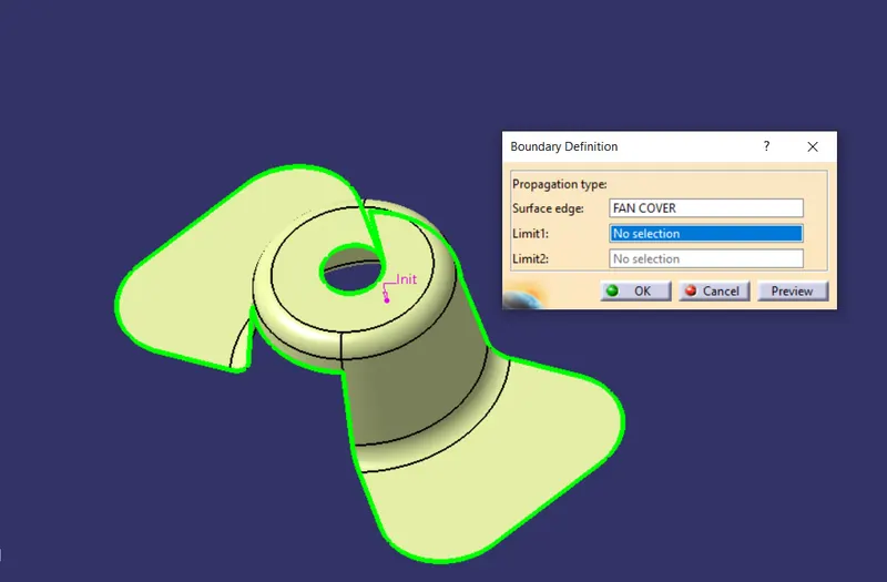
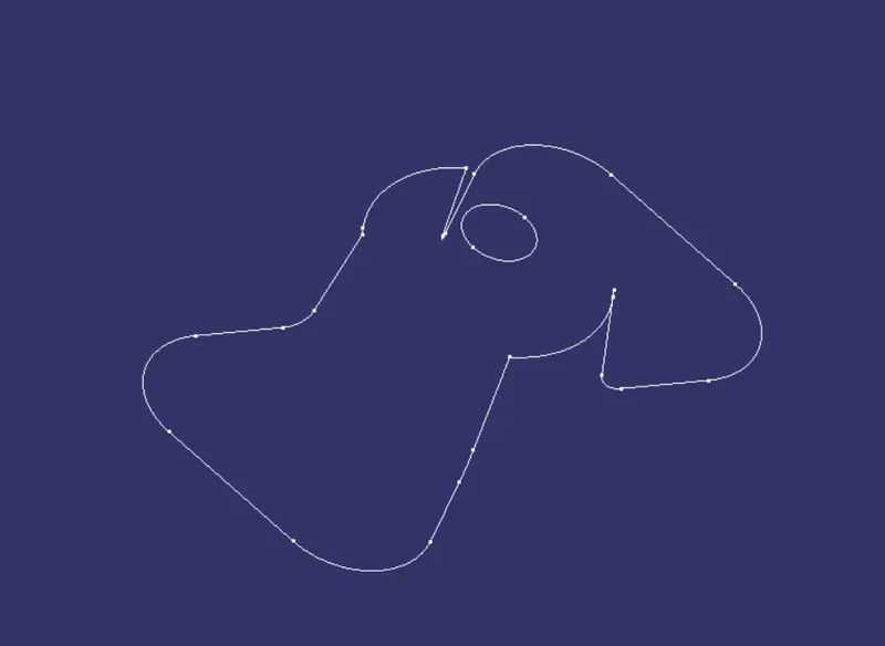
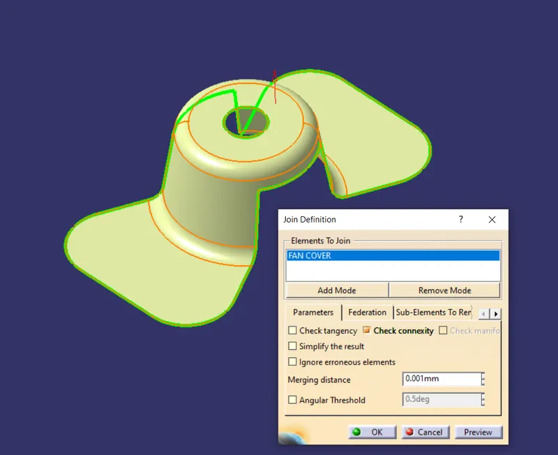
Create poit
Next step is to analyse the model in which direction is most suitable for tooling axis,look into all direction of model then decide the direction
In Isometric view of the model we can clearly see that hole on top face
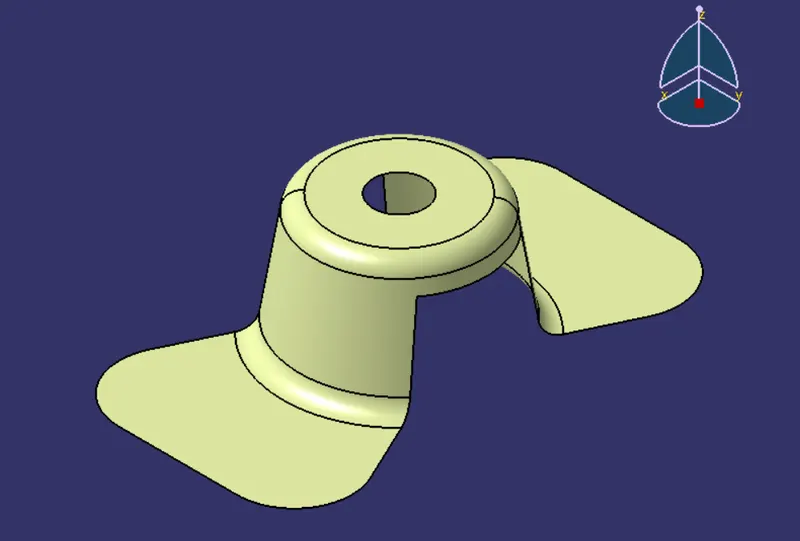
In X direction it is difficult to clear the hole
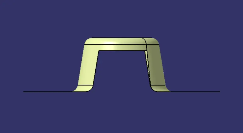
In Y direction also it is difficult to clear the hole by tooling
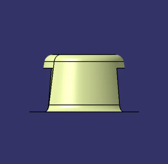
In Z direction the hole is clearly visible and we can create a one dummy tooling axis for reference purpose
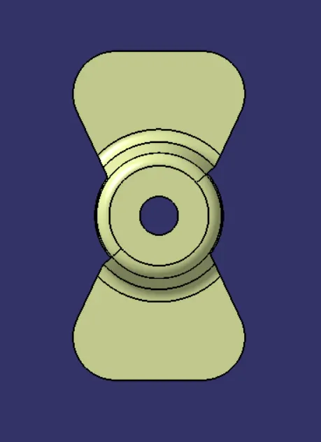
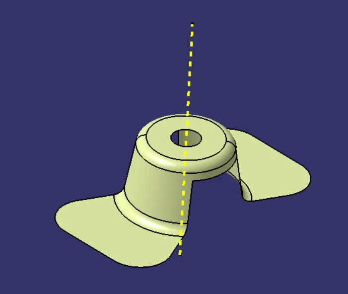
Next step is to create a bisecting line in X direction and in Y direction
Create point exactly it has to lie on the circle centre after that create a one axis system on the same point.
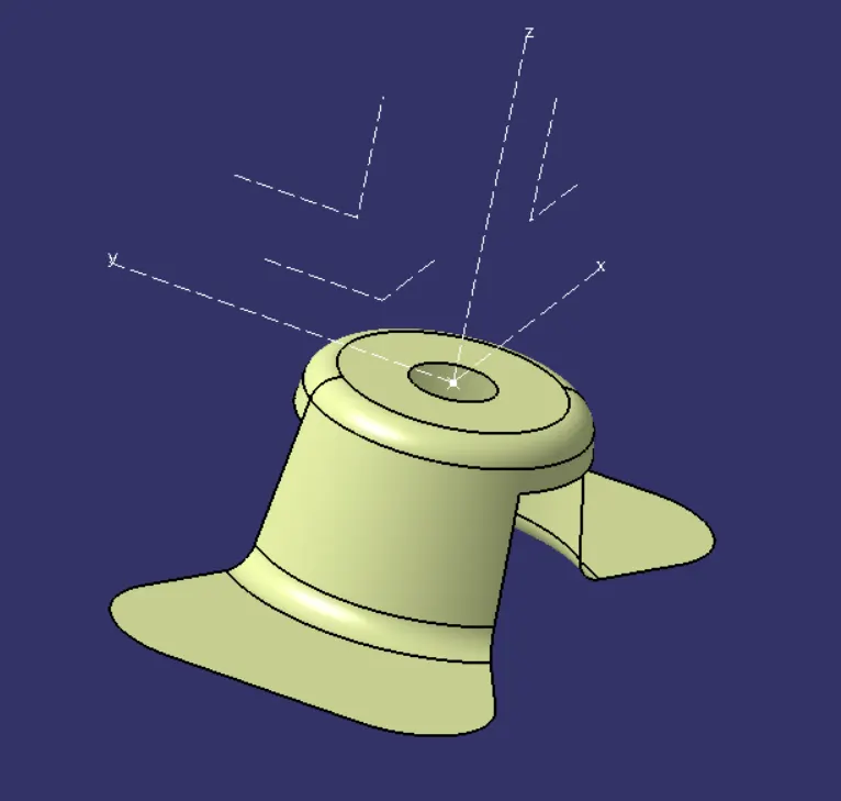
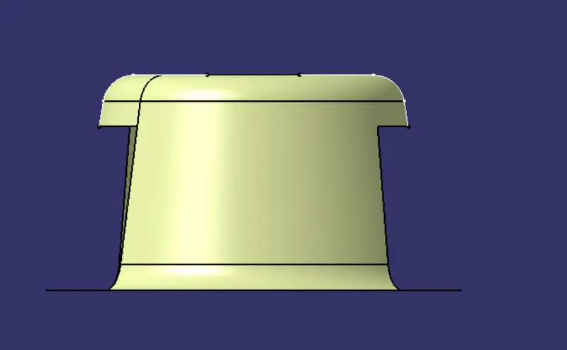
Intersect the ZX plane with class A surface now we will get intersection line,look where this intersection line creating problem,we are seeing two surfaces creating a problem while tooling so we have to create a line by selecting a point to point option.Below images shows the two lines and bisecting line created using this two lines.This is X direction tooling axis.
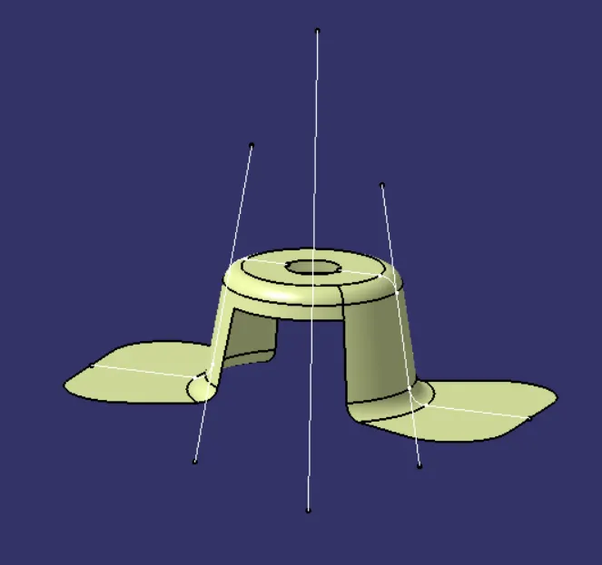
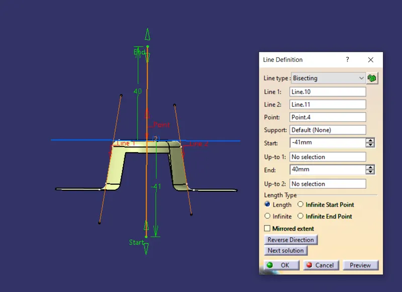
Similarly create the tooling axis in Y direction by intersecting the class A surface with YZ plane follow the same procedure
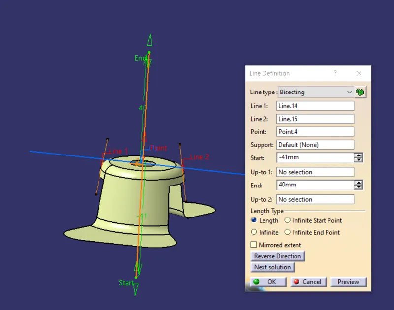
Now we bisect these two lines to get the exact tooling axis.

Draft analysis:
Go to Insert<Analysis< Feature Draft Analysis
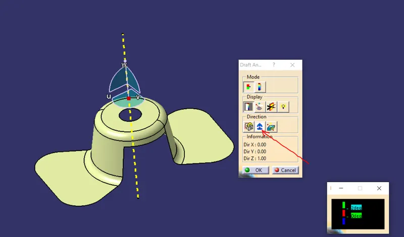
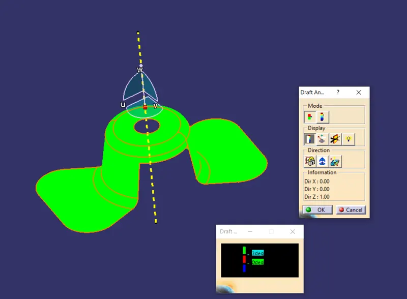
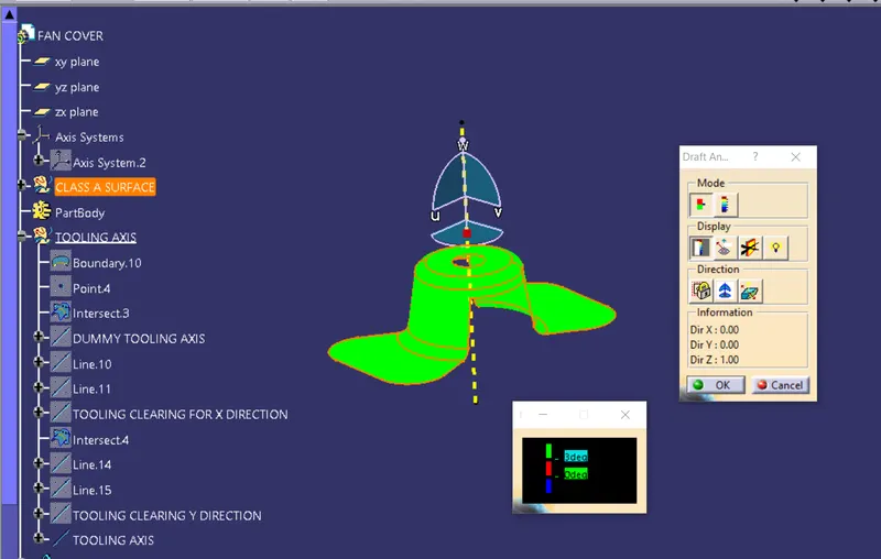
Click on the compass icon and adjust with tooling axis as shown below and click on the surface to get the draft results.
Then click on lock button
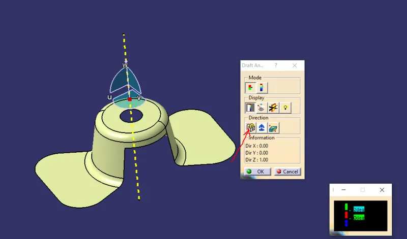
The red cross will appear click on the surface to analyse the result
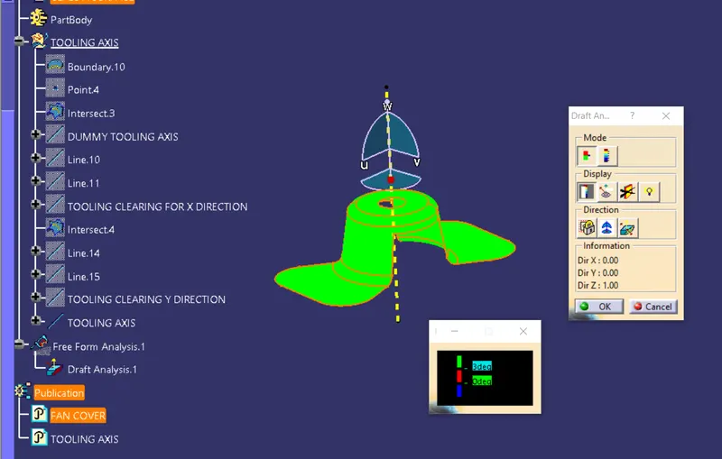
Green Means 3 degrees
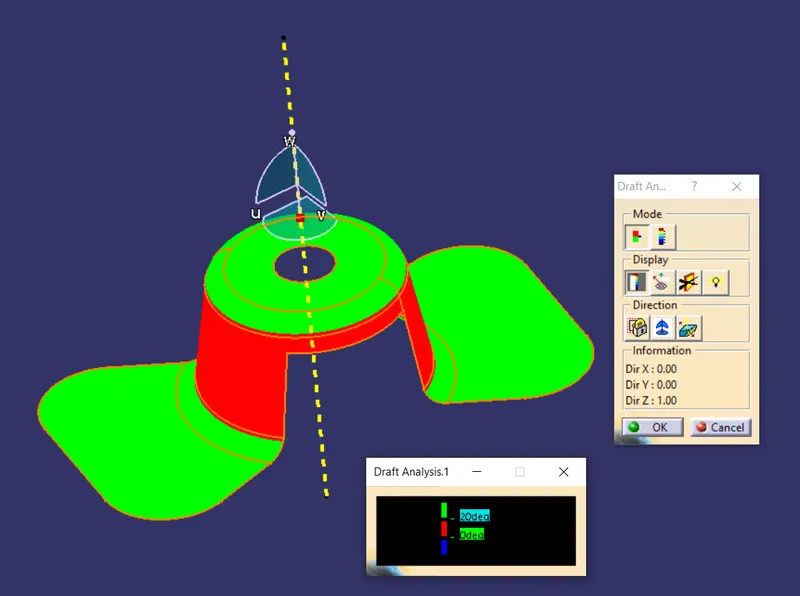
Red menas more than 3 degrees
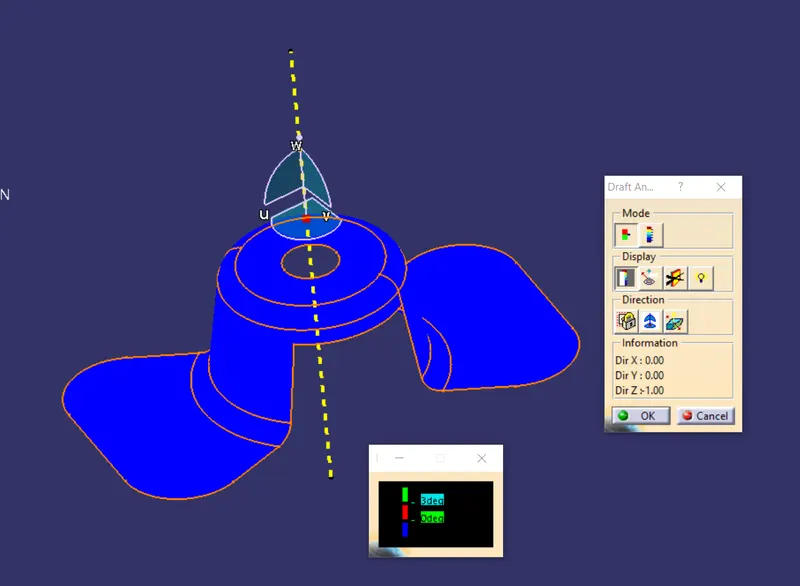
Blue means Negetive draft
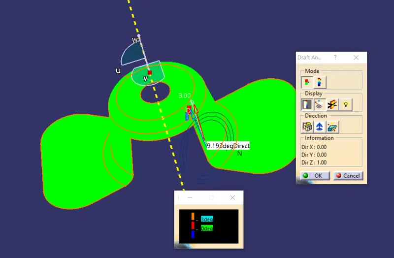
Through running point also we can analyse the part
Feature Tree
Conclusion:
Draft analysis performed on the part and found to be ok for moulding