Week 8 - Challenge 1 - Draft Analysis on a Fan Cover
Week 8 - Challenge 1 - Draft Analysis on a Fan Cover
Aim: To create tooling axis for the given Class-A Surface for the given model(shown below)
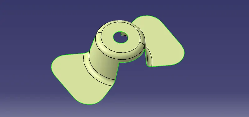
Class-A Surface: A class A surface is any of a set of freeform surfaces of high efficiency and quality. Although, strictly, it is nothing more than saying the surfaces have curvature and tangency alignment – to ideal aesthetical reflection quality. It describes the final production surface data for the aesthetic parts of the car.
Tooling Axis: It is the axis along which the mould moves to open or close the mould.
Procedure:
Step 1: Creating Dummy Tooling Axis
Initally a dummy tooling axis is created according to the Class A surface. Features of the Class A surface, such as Holes, Fillets, chamfers etc, is considered while creating the dummy tooling axis.
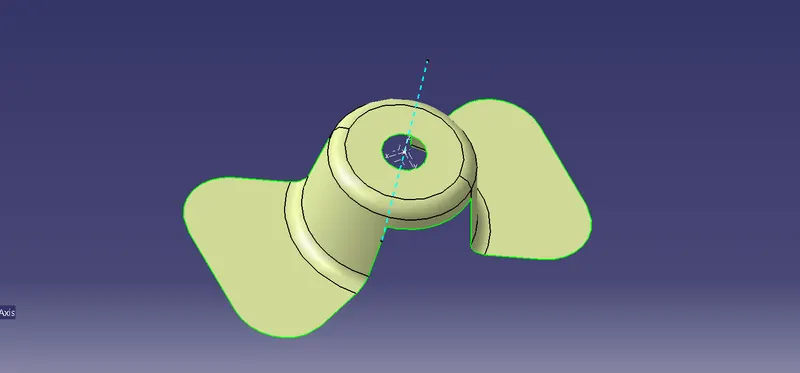
In the given model, there is a hole at its center and a dummy tooling axis is created with respect to it. To create a dummy tooling axis
Create a point on the center of hole> Create an axis on that point having a plane parallel to the top surface> Create a line point-direction- select the circle center, select z axis as direction(Refer the image below)
Step 2: Create X and Y Tooling Axis
X and Y Tooling axis is created so as to create effective tooling axis for the component. This done to avoid faliure of surface due to draft angles. If the angle between the Actual or effective tooling axis and side walls is lesser than the draft angle then it is difficult to mold. Hence tooling axis is created using the side walls from x and y direction and combining both to get effective tooling axis.
To create X Tooling Axis for the given component
Create an Intersection curve between the xz plane and the fan cover> Create a Line using the two points of the side walls of the fan cover on both sides> Create a new bisecting line between the two newly created lines> This will be the Tooling axis for x direction.
Similarly for the Y direction Create an intersection curve between the yz plane and the component and follow the rest of the above procedure.(refer the below image) Now to create effective tooling axis create a bisecting line between the x and y tooling axis.
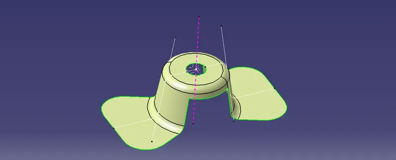
Image 2.1 X Tooling Axis
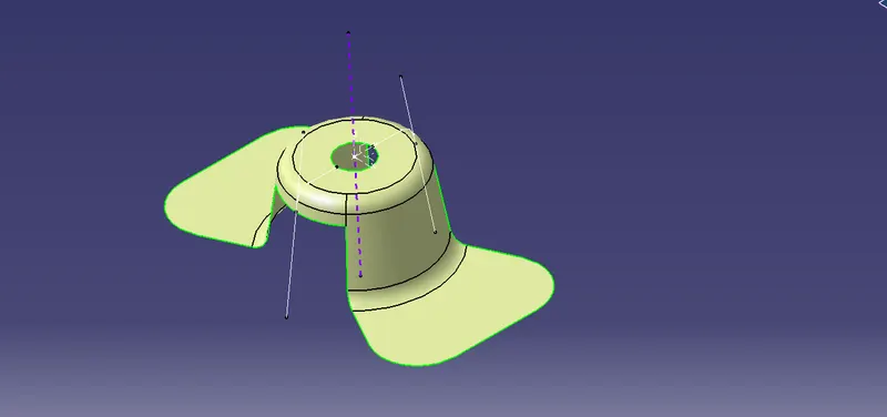
Image 2.2 Y Tooling axis
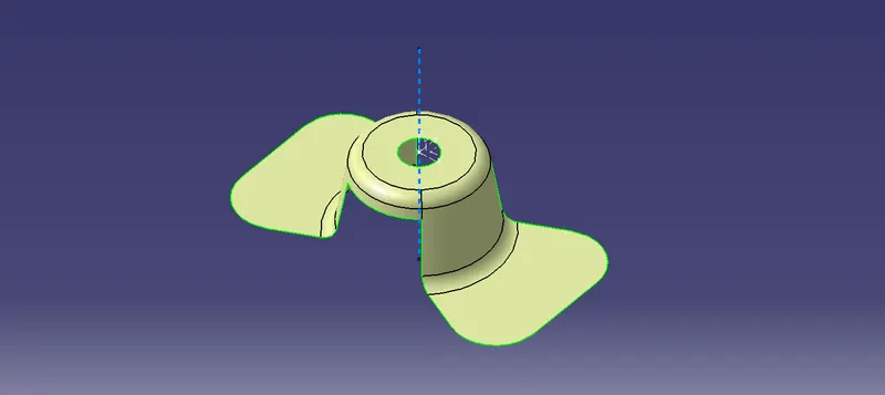
Image 2.3 Combined Tooling axis or Efective tooling axis.
Conclusion: The given model is checked for surface errors(connectivity) and created Tooling Axis using X and Y tooling axis for the mould creation.