Week 8 - Challenge 1 - Draft Analysis on a Fan Cover
DRAFT ANALYSIS OF FAN COVER
OBJECTIVE
The objective is to design check the draft angle of part surface from the determined tooling direction.
DRAFT
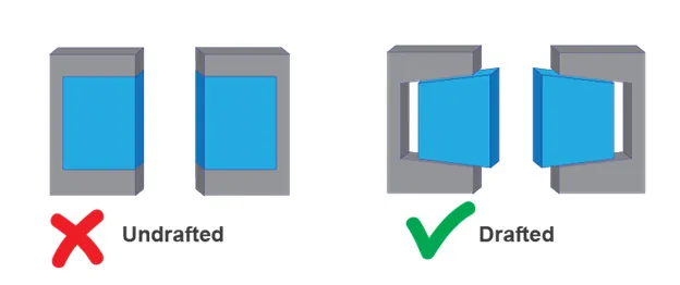
Draft is an angle given to the part surface which makes the ejection of part easier from the core and cavity after solidification. The nominal draft angle for plastic components is 3 degrees.
CONNECTIVITY CHECK
After receiving the class A surface from the studio, it is driven for connectivity check. This operation can be performed using join command. Also by creating the boundary surface we can check the connectivity. This is the minimal criteria check, that the class A surface should be in point continuity. If the is any miscellaneous surface or discontinuous surface it need to be rectified.
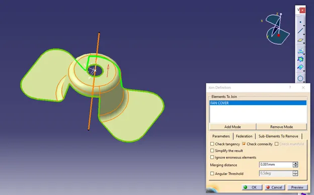
Continuity check using join command.
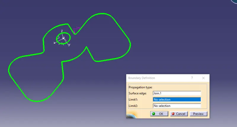
Continuity check using boundary command
DETERMINING TOOLING AXIS
TOOLING AXIS
This is the axis or direction along which the plastic part is drawn. All surfaces and features of the final part are drawn with respect to the tooling axis.
SELECTING THE TOOLING DIRECTION AMONG X, Y & Z
X- Direction
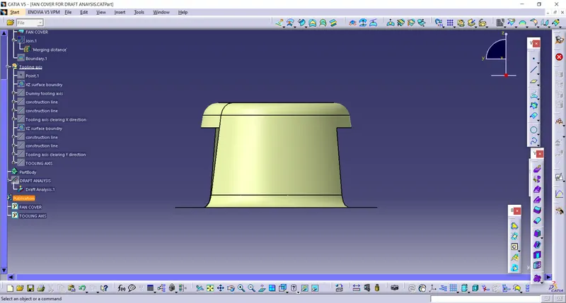
In this direction we need to check the drawing feasibility of the plastic part. Since the top surface is in flat state we cannot draw the part and eject it, also we need side core to produce the hole on top of it. This adds up cost, therefore direction X is not desirable.
Y-Direction
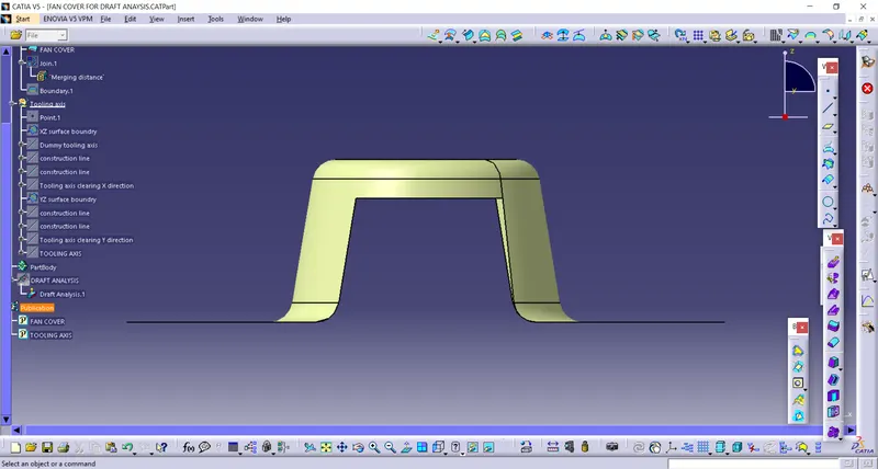
In this direction also the top surface is in flat state we cannot draw the part and eject it, also we need side core to produce the hole on top of it. This adds up cost, therefore direction Y is not desirable.
Z-Direction
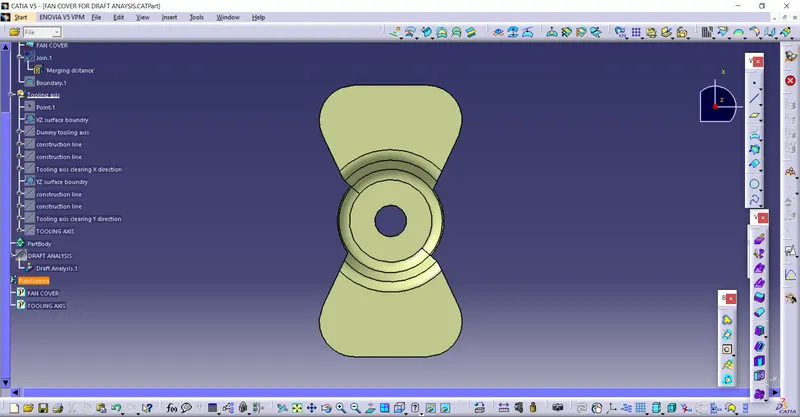
In this direction almost all surface are perpendicular to the direction Z. only the side surface are parallel but that too has a draft angle of 9 degrees. This draft angle helps in easy ejection of the part. The top hole can also be produced without side cores. Therefore this direction is chosen a tooling direction.
CREATION OF TOOLING AXIS
The tooling axis is created using bisecting method.
XZ surface boundary
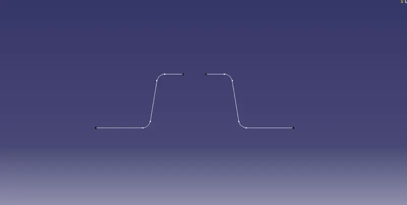
The nearest parallel surface to Z direction is chosen and extended for bisecting.
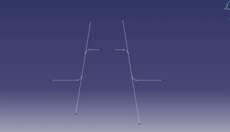
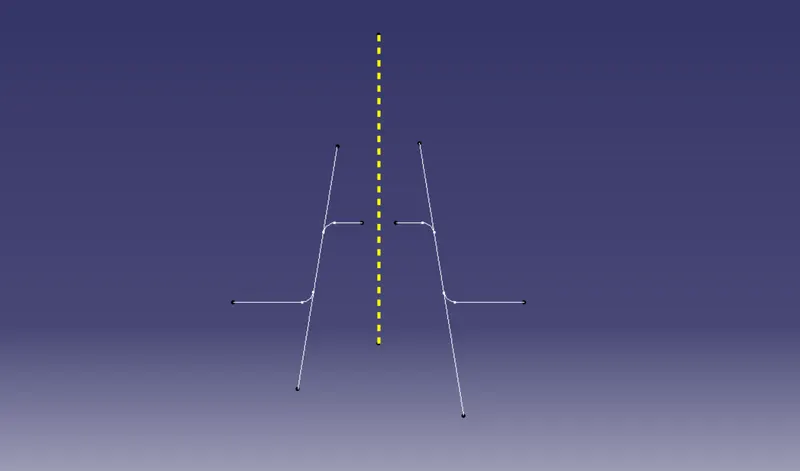
After bisecting the extended lines we get the tooling direction which clears the ZX plane surface.
YZ surface boundary
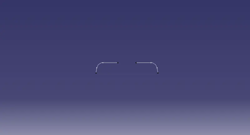
This is the YZ plane intersecting surface boundary.
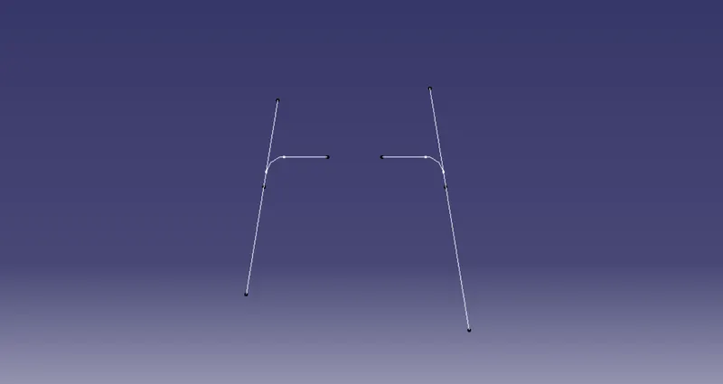
Selecting the parallel surface and extending it for bisecting.
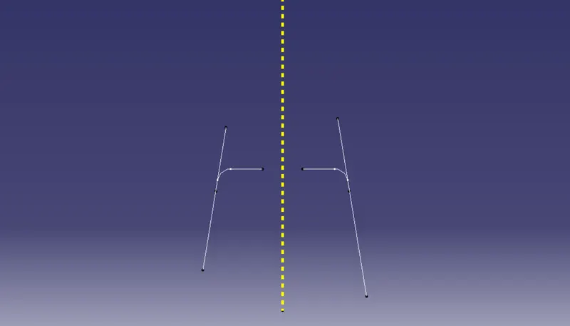
After bisecting the tooling axis which clears along YZ surface is formed.
The final tooling axis is created by bisecting the tooling axis generated in XZ and YZ plane
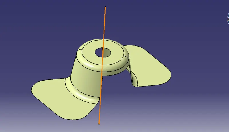
This tooling axis is the drawing direction for the plastic component.
DRAFT ANALYSIS
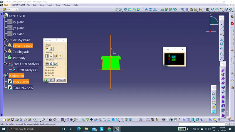
By selecting the compass and snapping it with the created tooling axis we can start draft analyzing. The typical draft angle for plastic components were 3 degrees. I set the limiting value as 3 degrees. Therefore if any surface less than 3 degrees were pointed red and blue. Green surfaces are greater than 3 degrees.
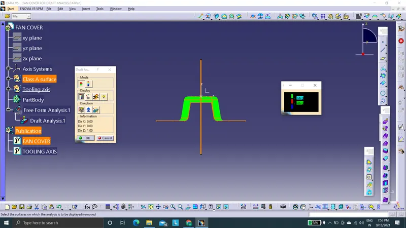
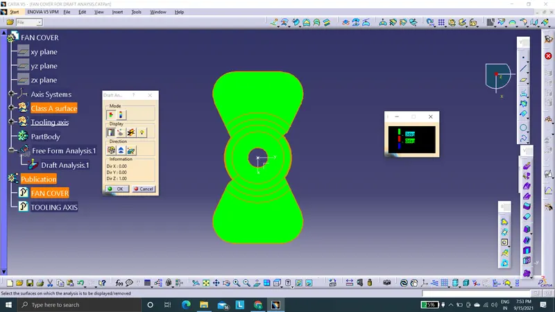
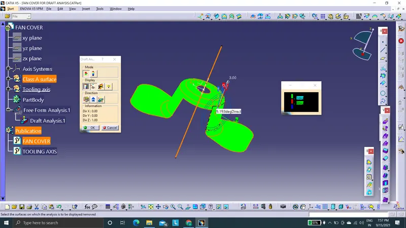
In this the running point draft angle mode the side surface of fan cover got a daft angle of 9 degrees, which is 3 times the limiting value. Therefore there is no problem in drawing the part.
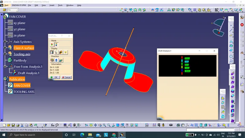
This is the full analysis mode.
TREE STRUCTURE
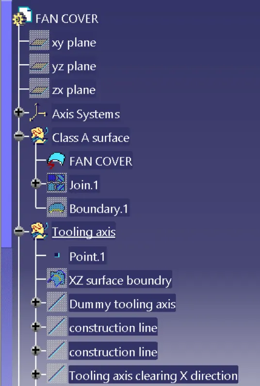
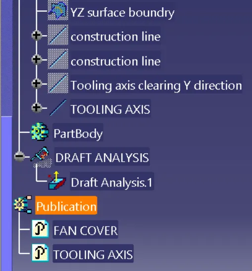
CONCLUSION
The darft analysis is done on fan cover and it is published.