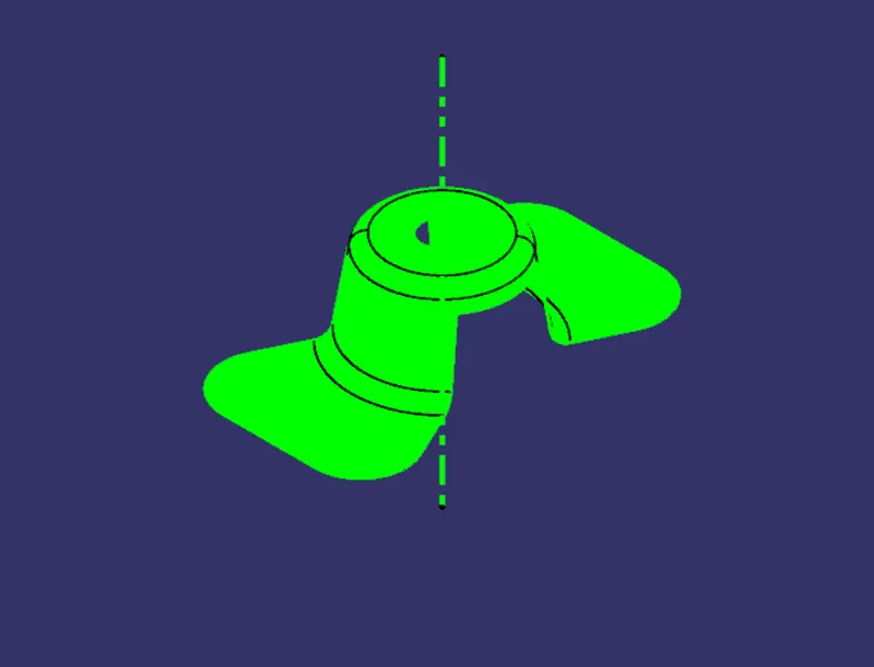
Draft Analysis on a Fan Cover
DRAFT ANALYSIS
Draft Analysis:
Draft Analysis is a method used to check if a part can be easily removed from the mold. When making a part that will be molded, the draft analysis will verify that all surfaces (drafts) are favorable for the part being pulled from a cavity. This type of analysis is performed based on color ranges identifying zones on the analyzed element where the deviation from the draft direction at any point, corresponds to specific value. In case of more complex parts that need multiple cores or slides, it becomes very helpful to highlight areas which might not be favorable for easy removal of the part from the mold.
Tooling Direction:
Tooling direction is basically the direction in which the mold opens and the 2 halves of the mold get separated. The draft angle to surfaces and features is provided with respect to tooling direction to make it easier for removal of the part after the mold opens. Once we have the tooling axis, it becomes easier to design the part features accordingly to make it manufacturable. While providing every particular feature we should consider draft angles to be given with respect to tooling direction.
Creating Final Tooling Direction (Axis):
- For obtaining the final tooling direction, we will consider all the 3 axes and view the part along them. Choose whichever direction feels appropriate.
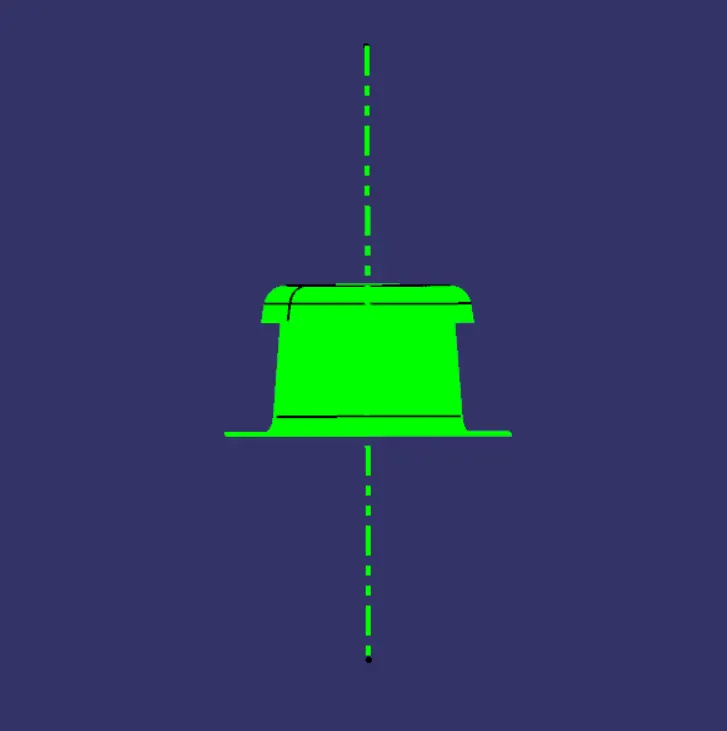
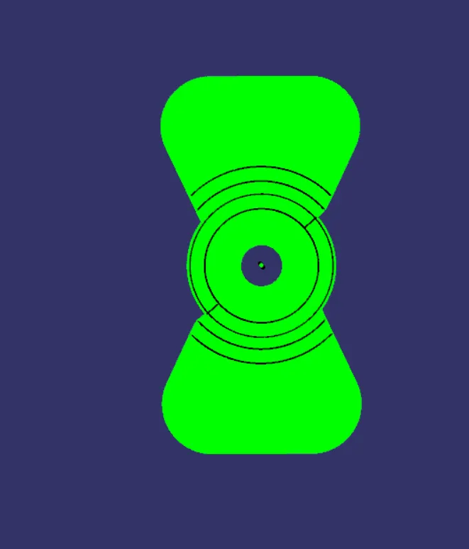
- For example, in this case, after viewing the part in different views, we can conclude that z-axis is appropriate for our tooling direction.
- We create a dummy tooling axis here along z axis and through a point at the top hole in the part.
- Then we need to verify if this is the correct tooling direction for the given part by other method. For that we will take clearing axes by considering x axes and y axes.
- For x direction tooling clearing, we take intersection of the given surface body in a direction perpendicular to x axis.
- Then we extend the lines in intersection that are inclined to z axis and as shown below, create a line by bisecting these 2 lines.
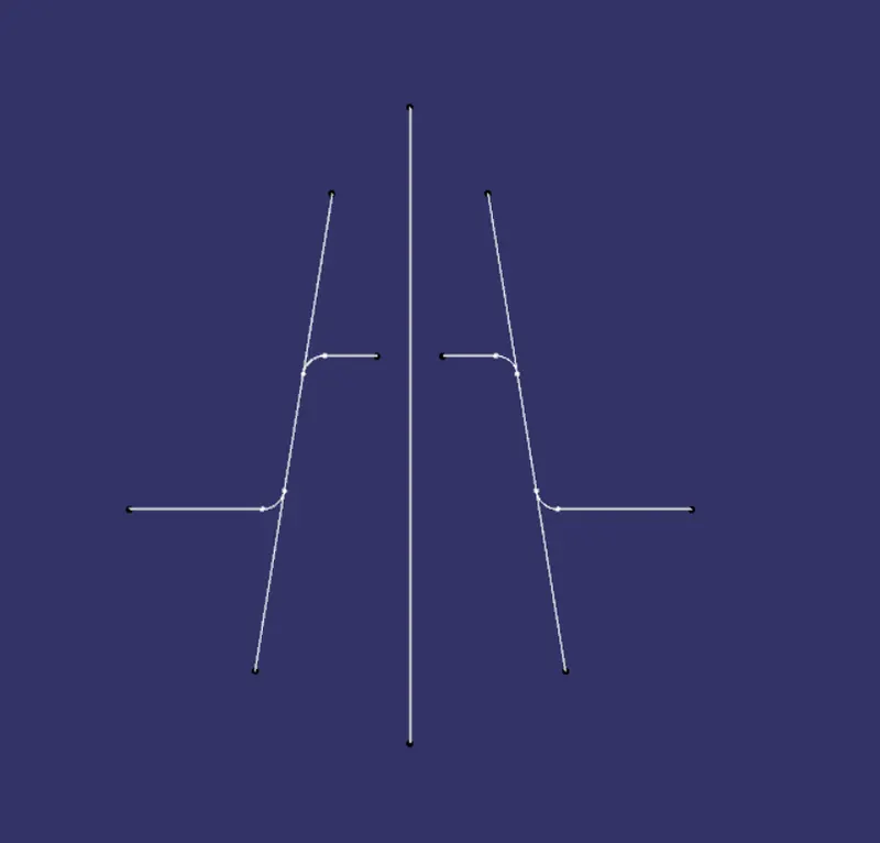
Fig.1 Sketch for X axis tooling clearing
- Thus, the bisector line obtained is the X direction tooling clearing axis.
- Now similarly, for Y direction tooling clearing, we take intersection of surface body with a plane perpendicular to y axis.
- In the intersection sketch obtained, we extend the lines that are inclined to z axis as shown below and create a line by bisecting these 2 lines.
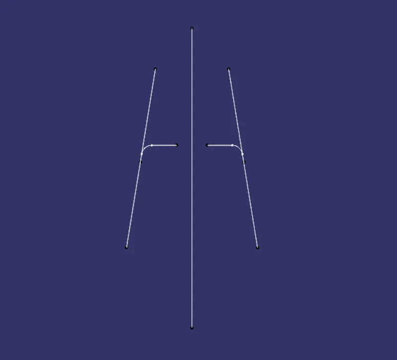
Fig.2 Sketch for Y axis tooling clearing
- Thus, the bisector line obtained is the Y direction tooling clearing axis.
- Now, we create a line by bisecting these 2 lines. Thus, we obtain the final tooling direction and axis along it.
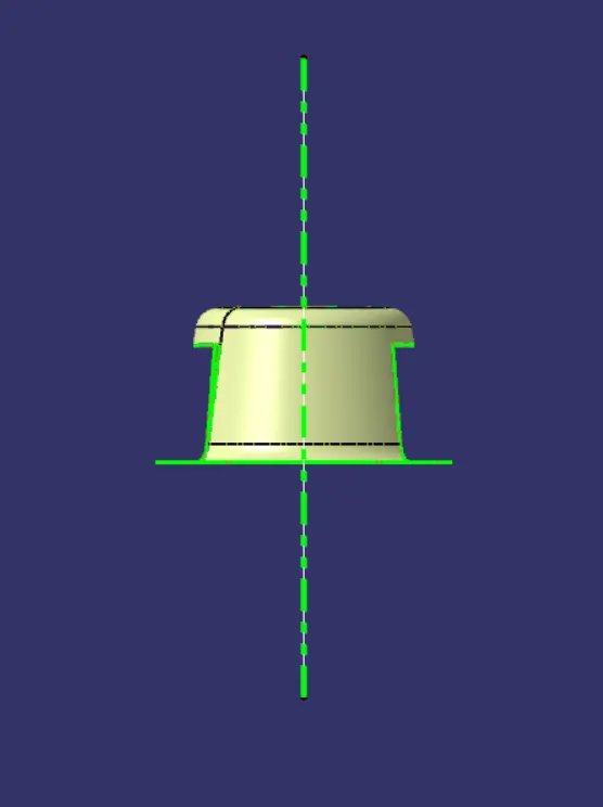
Fig.3 Final tooling direction
IMAGES
Draft Analysis and color scale variant
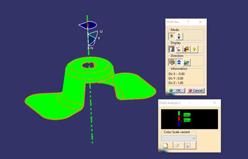
Tooling Direction
Model different views
Front view
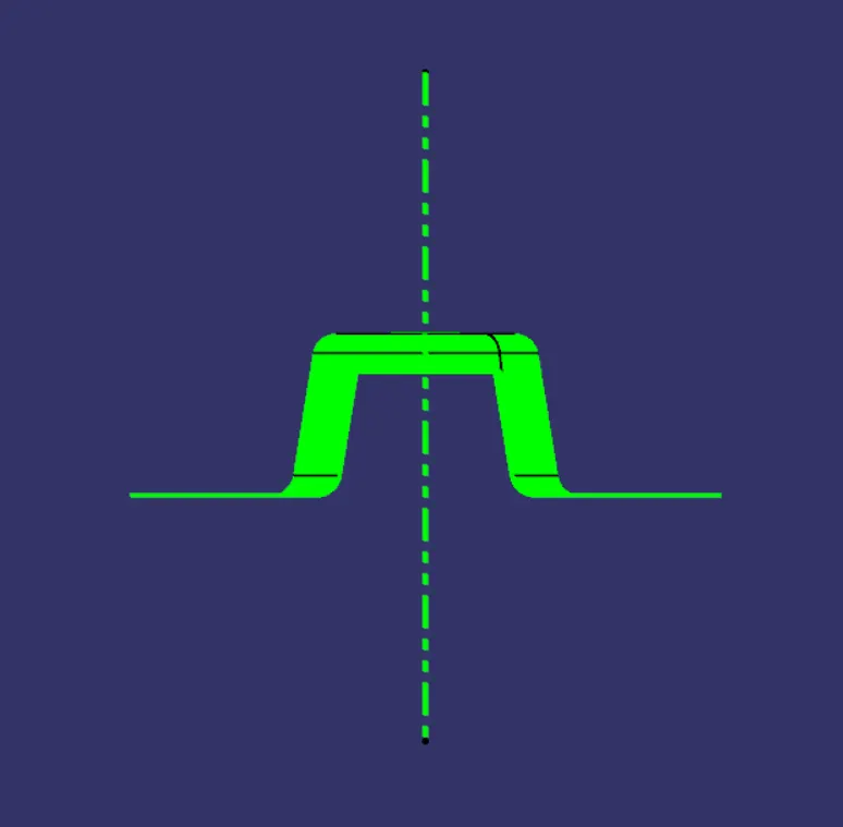
Side view
Top view
Isometric view