Week 8 - Challenge 1 - Draft Analysis on a Fan Cover
DRAFT:
Draft is providing angle or tapers on product features such as wall ribs,posts or bosses that lie parallel to the direction of release from the mold eases part ejection.
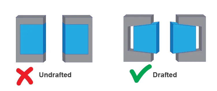
DRAFT ANALYSIS:
The Draft Analysis command enables you to detect if the part you drafted will be easily removed.Draft analysis is performed based on color ranges identifying zones on the analysed element where the deviation from the draft direction at any point corresponds to specified values.Draft is required on all parts in the direction of mold movement in order to allow parts to realease or eject from the mold properly.
Most applications requires minimum draft angle of about 0.5° to 1°,however 3° draft angles are widely accepted for cost saving purpose.7°draft angles are given to textured surfaces like instrumental panels.Minimum possible draft angles are given to screw bosses ribs and stiffner due to their critical nature.
TOOLING AXIS:
Tooling axis is the direction in which the mold opens and closes.part draft are given along this axis.
OEM Rules for feature draft analysis:
The truth is no single draft angle can be applied to all part designes.Factors like wall thickness material selection,ejection,shrink rates,finish/texture,wall depth and manufacturing capabilities all come into play.
Guide line for draft:
- 5° on all vertical faces is strongly advised.
- 1-2° degrees work very well in most situation.
- 3° is minimum for a shutoff.
- 3° is required for light texture.
- 5 °are more is required for heavy texture.
Procedure:
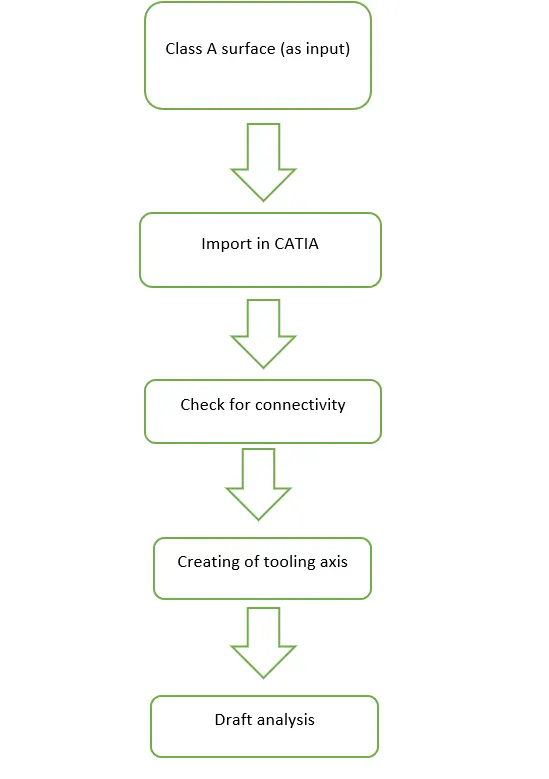
Draft analysis of fan cover:
Step 1:Design check on class-A
After receiving the class-A for the fan cover check the connectivity of the surface using joint,boundary tools .
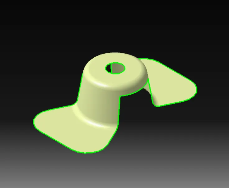
Step 2:Determining tooling axis
Creating a dummy tooling axis along the best possible direction as per the classs A .In this case we have chosen Z axis as dummy as it doesen’t interfere with any slots or holes.
Create an axis system on this line using suitable point
Create an intersect between the two planes(XZ and YZ) and the class A surface
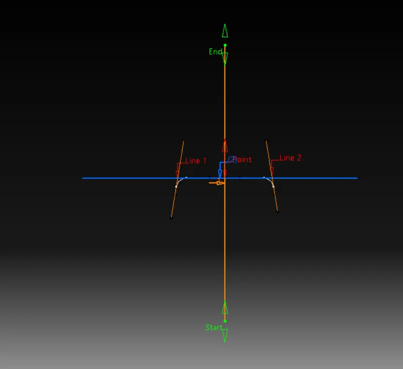
The belove image indicates the intersection between class A surface and XZ
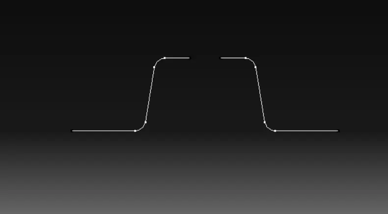
The side wall of the fan cover lines are extended
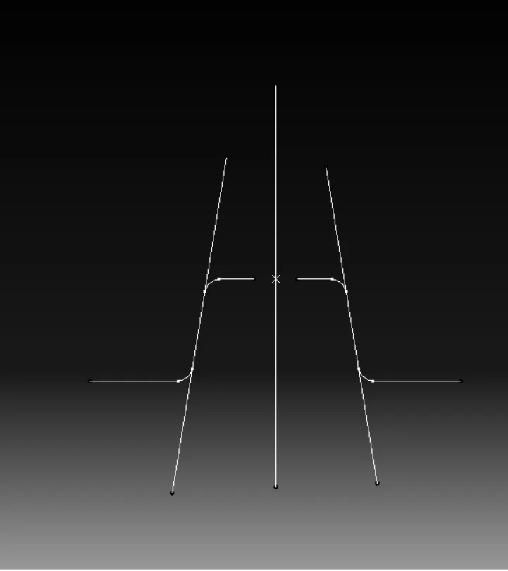
Bisecting lines are taken between side line and the centre point and the orange line indicated the tooling direction
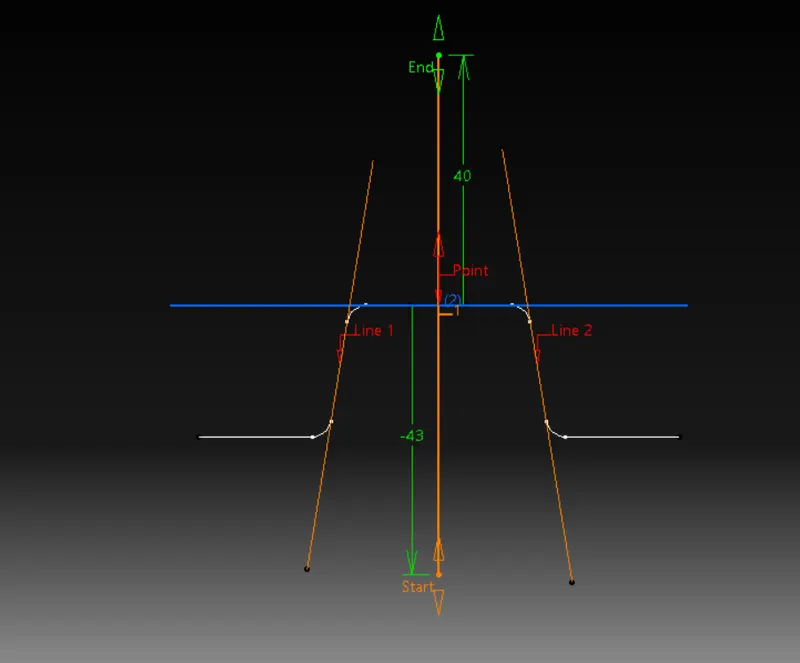
This image indicates the intersection between class A surface and XZ plane
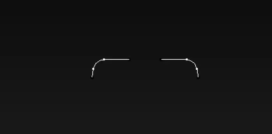
The lines are extended
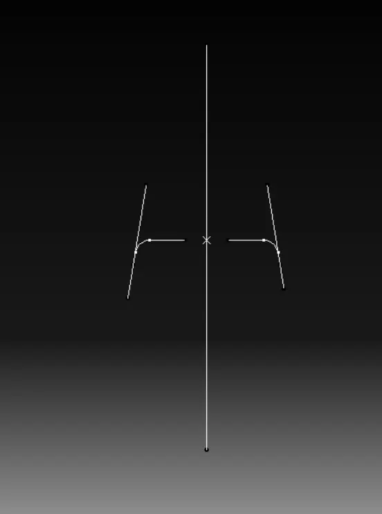
Bisecting lines are taken between side line and the centre point and the orange line indicated the tooling direction
Step 3:Draft analysis
Customize the view mode to material
Go to feature draft analysis move the compass to the tooling axis and now select the fan cover
The different colours in the draft analysis indicates different draft angle
Use lock tool to lock the direction of the tool axis
The compass made to align to tooling direction line
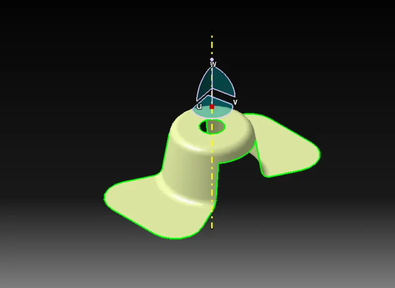
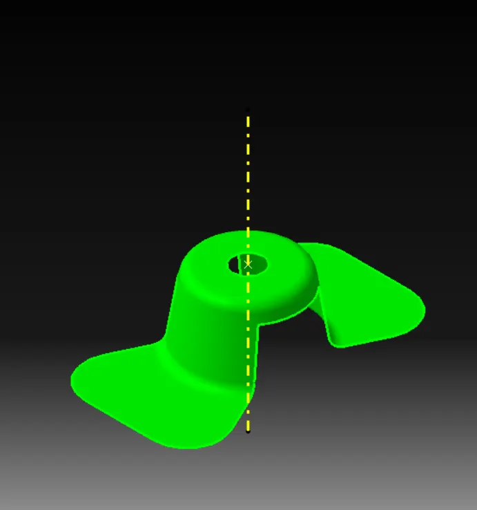
The yellow line in the image indicates tool axis.Each colour indicates different draft angles.
Conclusion:
The green colour indicates the positive draft angle this indicates that the part can be manufacturable.