Week 8 - Challenge 1 - Draft Analysis on a Fan Cover
DRAFT ANALYSIS OF FAN COVER CLASS A SURFACE:
Draft Analysis:
During designing of any automotive component, a small draft is given to the sides to make sure that while manufacturing by any method, say compression moulding of a plastic part, the part should come out of the core and cavity easily without getting damaged. Hence while designing it is always advised to give minimum of 0.5 to 3 degree draft incase of a plastic part to be produce efficiently. this draft made has to go through Draft Analysis in order to verify the draft which is given can beuseful to produce the part. Hence Draft analysis is made.
Draft Analysis of a Plastic Part (Fan Cover):
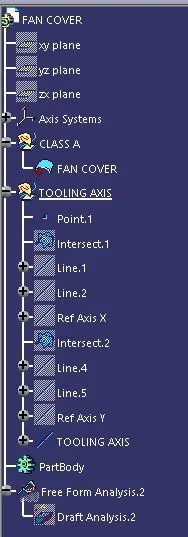
Tooling Axis can be created if we found the correct direction to tool travel to produce the part without use of side cores or adding any costs while producing the part. It can be acheived by normally looking at the surface and assuming the best direction.
To begin the draft analysis, we make sure that the given surface is perfectly joined together without any improper spaces between it. This can be done by using joibn option to ensure that the surface is joined properly.
CREATING TOOLING AXIS:
Tooling axis is the axis where the direction of the tool travel while manufaturing the component. Hence the tooling axis can be a reference to check the tooling direction and analysing the draft.
CREATING INTERSECTION LINES FOR TOOLING AXIS:
First, we create a temporary tooling axis in the X and Y directions by creating an axis system at a point, from this point the intersection lines will be created for the reference. after creating the lines, we bisect thse lines to get the "Ref Axis X" (See Tree structure) line for Tooling Axis as shown below.
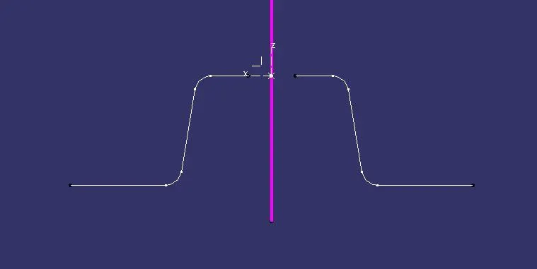
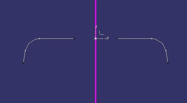
Simillarly, in the Y direction, by creating the intersection lines and bisecting it, we get the Ref Axis Y for creating the Tooling Axis.
DRAFT ANALYSIS:
After getting the X and Y ref axes, simply bisect these two lines to get the required TOOLING AXIS. (Pink Colur Line). This is the tooling axis for the product.
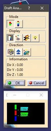
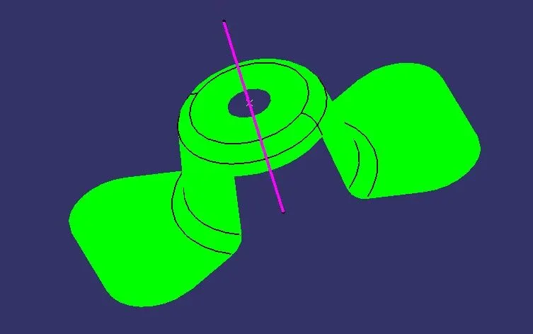
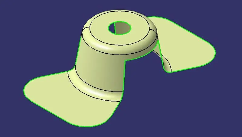
As in the First image, it shows that the green color represents the 2 Deg draft which satisfies the draft analysis and the surace is all green, and this surface is ready to be designed as it satisfied the minimum draft (0.5 Deg - 3 Deg) requirement. Hence The given Class A Surface is ready to be designed and manufactured.