Week 8 - Challenge 1 - Draft Analysis on a Fan Cover
FAN COVER DRAFT ANALYSIS REPORT
- CHECKING FOR SURFACE CONTINUITY
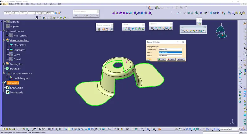
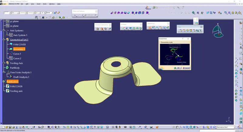
Once the fan cover geometrical set (class A surface) is opened in CATIA V5, we need to first check if the surface is continuous and there are no gaps in the surface. In order to do this click on the Boundary command in surface work bench and then click on the fan cover surface. The boundary output should be now disassembled using the disassemble command and display both domains should be selected. We get two curves as output and upon inspection they seem to be continuous and thus we can say that the surface is continuous with no gaps. This is the first design check.
- Creation of Tooling axis
The next step is to create the tooling axis for the surface. The tooling axis is the direction along which the core and cavity will move so that the plastic part can be tooled or produced. If the plastic part can clear the tooling along this tooling axis then the plastic part is considered to be toolable or can be produced.
The first step is to create an axis system at the center of the plastic part. For this create a point at the center of hole on the plastic part and then create an axis system at that point.
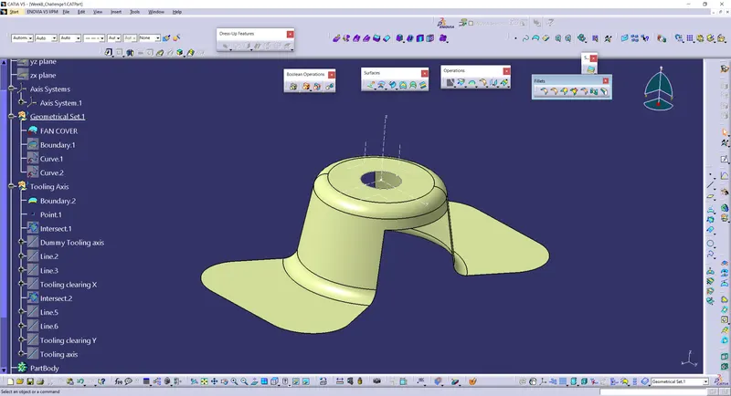
At first glance we can see that along x and y axis the plastic part cannot be tooled easily as there is a hole on the surface which would need a side core in order for the surface to be toolable. This makes it more expensive to prepare the mold. Along z axis the surface can be easily tooled.
To create the tooling axis we first need to create the tooling axis clearing in both X and Y axis and then bisect the two in order to get the final tooling axis.
Let us first start by creating a dummy tooling direction along the Z axis.
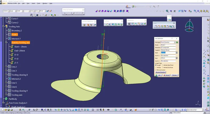
In order to create the tooling axis clearing X direction first we need to intersect the ZX plane with the fan cover surface. This will provide us with an intersection curve. Upon inspection of this curve we see that top and bottom flat curves pose no problem for tooling. The two middle slant curve needs to be checked for tooling. Hence we need to create lines along the slant curve and extend them a little bit on both sides. Then a bisecting line should be created between these two lines which we just created. The bisecting line would be the tooling clearing X direction.
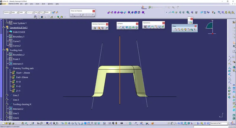
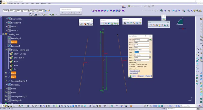
The similar procedure should be carried out to get the tooling clearing Y direction. This is done by intersecting the fan cover with YZ surface and the resulting curve is checked for tooling. Two lines should be created along the slant curves and then extended in both directions. A bisecting line between these two lines is created which the tooling clearing Y direction.
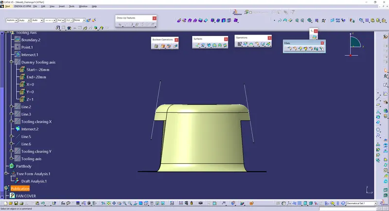
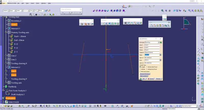
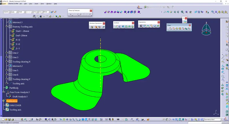
To get the final tooling axis for this surface we need to now bisect the tooling clearing X and tooling clearing Y direction. The resulting line is published in order to make it more accessible. To publish it click on the tooling axis and go to tools and publication. Now the draft analysis can be performed along the Tooling axis.
- DRAFT ANALYSIS
To begin with draft analysis click on insert – analysis – feature draft analysis.
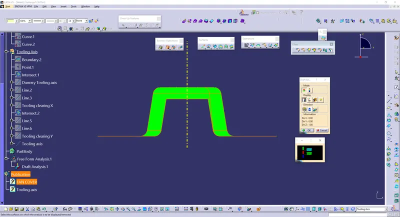
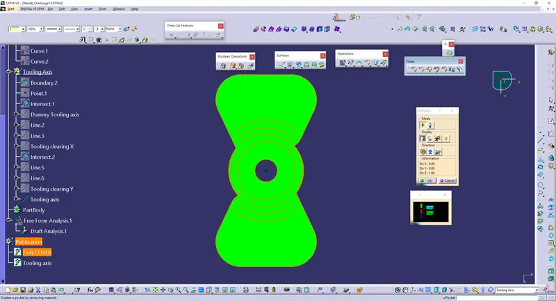
Two dialog boxes appear. The big dialog box is used to perform draft analysis and the color code dialog box shows the color code according to the draft angle range we set. Green is for positive angle, red is for zero angle and blue is for negative angle.
In the first dialog box click on the compass symbol and drag the global compass when the mouse pointer turns red and place it on the tooling axis.
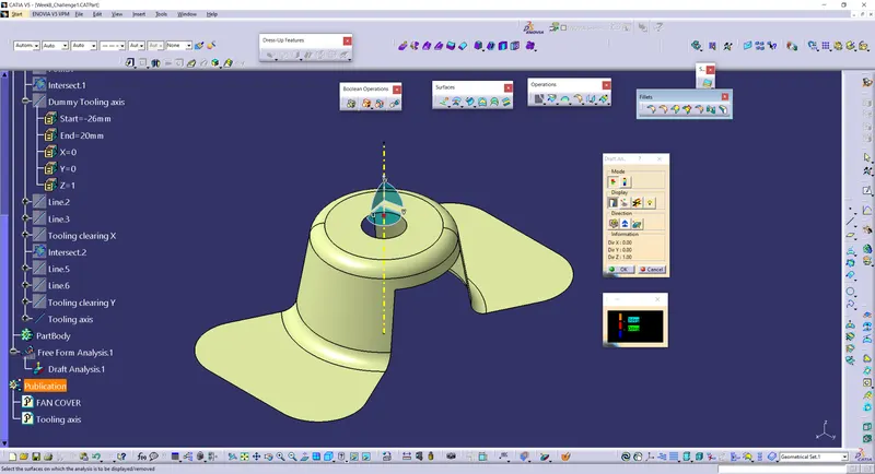
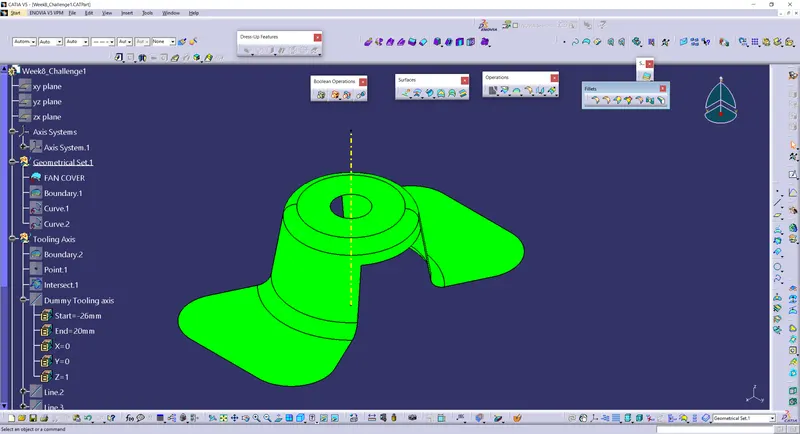
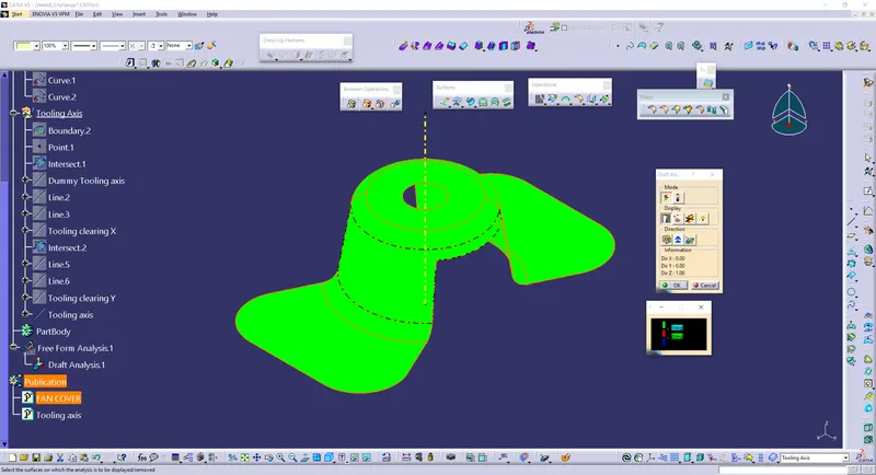
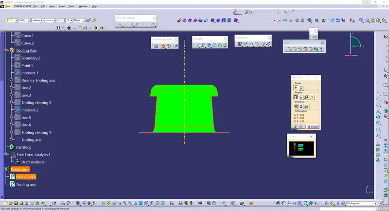
Next click on the lock symbol to lock the draft direction. Now click on the surface . We can see that the mouse pointer will be red and then we can click on the surface. We can now notice that the surface is green. This means that the draft angle which we have set for 3 degree is sufficient to clear the tooling. If we increase the draft angle to 10 we can see that some surfaces turn red which means it does not clear tooling for a draft angle of 10 degrees.
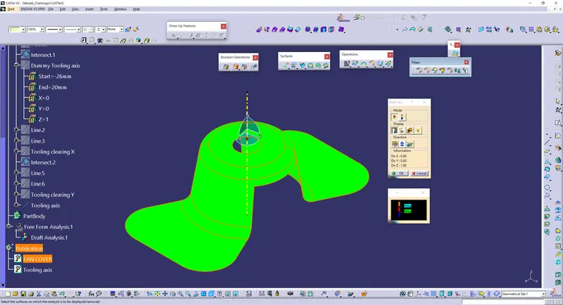
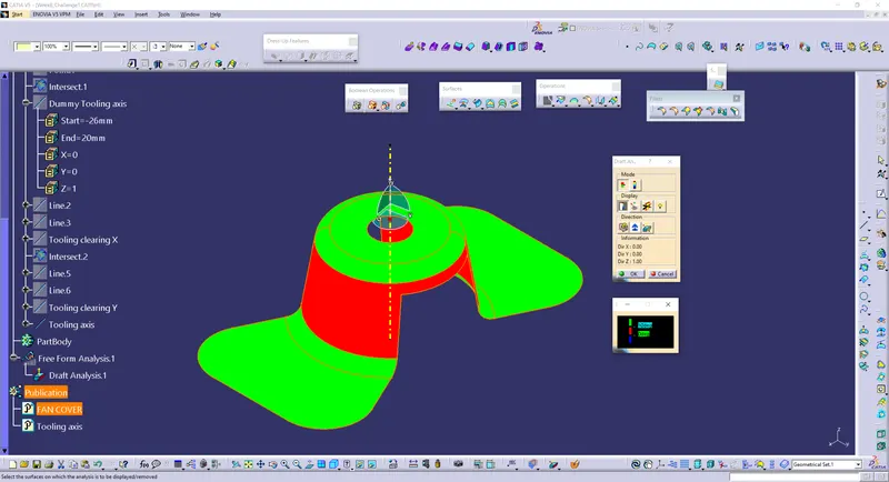
We can use the analysis under running point symbol to check the angle of the surface at any point to the tooling axis.
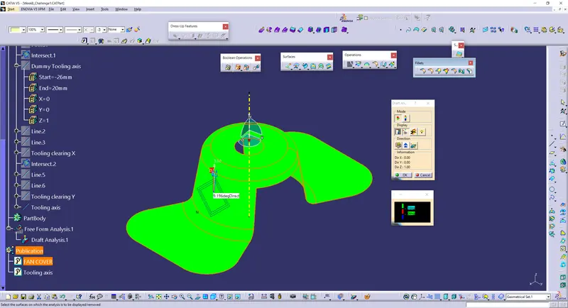
After the surface is fully green we can click ok.
 #
#