Week 8 - Challenge 1 - Draft Analysis on a Fan Cover
AIM:-
To create the tooling axis for the given Fan cover model meeting the requirements of the draft angle and perform the Draft analysis on the model.
OBJECTIVE:-
- To ensure proper tree structure is followed.
- To create Geometrical sets that should have a proper name based on the sketches present inside of them.
- To create all the sketches under the Geometrical set.
- To publish the Tooling Axis and Class-A Surface.
PROCEDURE:-
The given Class-A Surface is imported into CATIA V5.
TOOLING AXIS:-
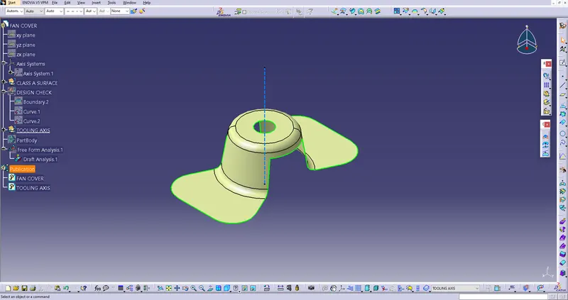
After importing the model is checked for boundaries using the boundary tool.
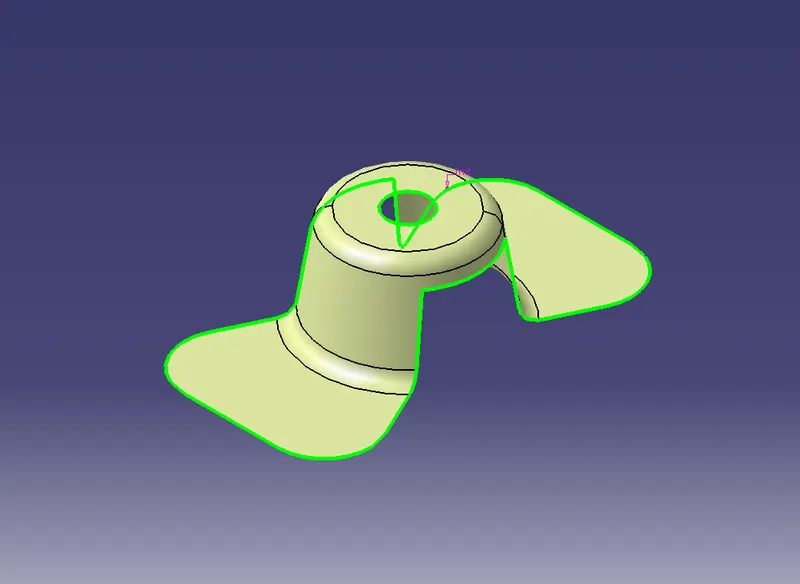
After checking the boundary that it has no gap in it, the Class-A Surface is moved ahead to create a tooling axis. To create the tooling axis, a dummy tooling axis is created in the Z-component.
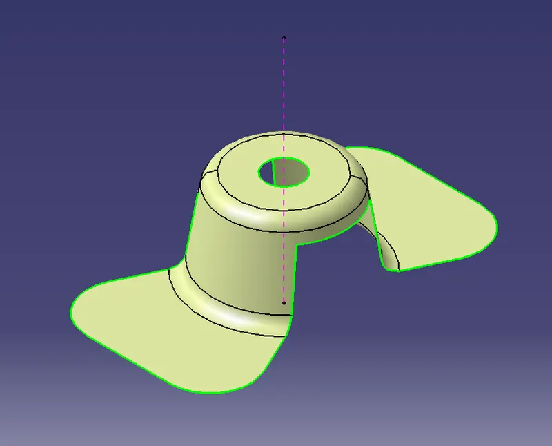
After the creation of the dummy tooling axis, the XZ axis is selected and the intersection tool is clicked to get the intersection of the Class-A Surface with the XZ axis.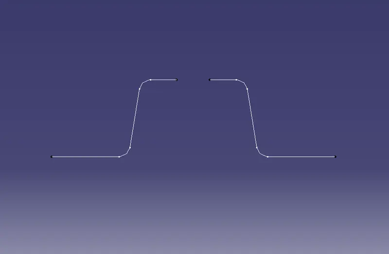
From this, the bisecting line is produced by creating a point-point line on both sides from the centre point (or) the axis system.
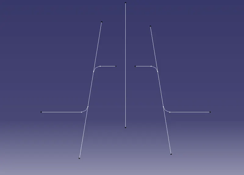
Similarly, by using the XZ axis the other bisecting line is drawn.
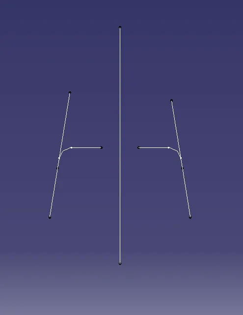
From these two bisecting lines, another bisecting line is drawn which is the tooling axis of the Fam Cover surface.
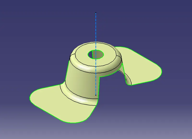
DRAFTING ANALYSIS:-
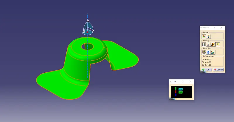
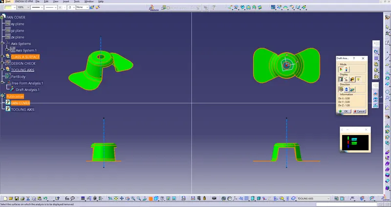
The draft analysis is performed by INSERT-->ANALYSIS-->FEATURE DRAFT ANALYSIS. To give the draft direction use the compass and align the Z-axis of it with the following axis which we created for the model. Once it is properly aligned, lock the draft direction. The red colour will be shown on the screen, select the fan cover and the current draft angle is displayed.