Week 9 - Attachment Feature Creation - Challenge 1
PROCEDURE -
DRAFT ANALYSIS -
- Before starting to work on the part we have to see the connectivity of class A.
- In order to create a tooling axis, we have to create lines in x-direction and y-direction and we have to bisect them to get the tooling axis.
- We have to take the axis system at the center of the surface (class A) and we have to intersect them with xz direction of the planes. so that We get a wireframe in the desired
direction in which we have to create lines and bisect them. so the lines we get after the bisection it is known as the tooling axis.
We have to do this for the other direction (or )plane. - After getting the tooling axis we need to publish them.
- In order to do the draft analysis, we need to change the material, which is present in the view toolbar.
a window will open, click on material then ok. - To open draft analysis, go to (insert - analysis - draft analysis )
- After opening the draft analysis tool
we have to click on the compass which is present in the draft analysis table and find the compass, drag it towards the tooling axis and design them.
Click on the lockbox then ("x") this symbol will arise, go to the object and click on them.
we can measure the angle of object by clicking on the eye symbol which is present on the display .
we can get the result by clicking the options that are present in the model.
Creation of a Rib
- First, we need to select a plane, and then we need to extract it.
- Next, we need to open a sketcher on that plane and we need to draw a line and extrude them.
- After extruding we observe a plane, then we need to go to the part body, and then we need to use a thick surface so that the solid surface is formed.
- Since the ribs are the different body we need to add them to the main body so that we can use boolean commands and join them. after joining we need to give the fillets for the ribs.
- And finally, we need to do a draft analysis for these ribs.
- Rules for creating a rib ------
Rib thickness at the tip = >=0.75
Rib Draft = >=0.5 degree
Rib radius(fillet) = 0.25 maximum
Rib Thickness (w) = 0.4*t (where t is the thickness of the wall)
Rib Root thickness = >=40% of wall thickness
Rib depth or height = <=5t (where t is the thickness of the wall)
Rib spacing = 2t(where t is the thickness of the wall)
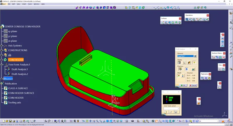
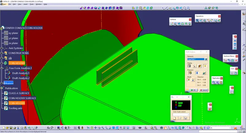
IMAGES SHOWING THE RIBS AND DRAFT ANALYSIS -
IMAGE SHOWING THE DRAFT ANALYSIS AND TOOLING AXIS
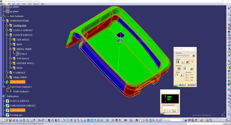
IMAGE SHOWING ,THE IMAGE OF A SKETCH AND SURFACE -
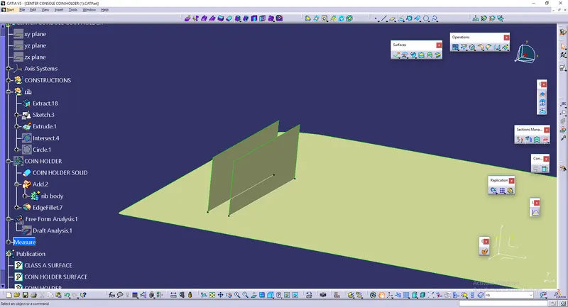
IMAGE SHOWING ,THE IMAGES OF RIBS -
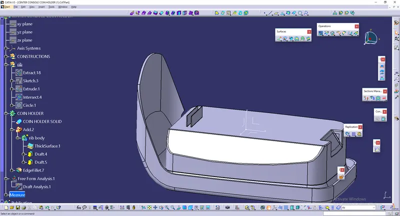
IMAGE SHOWING THE RIB ROOT THICKNESS -
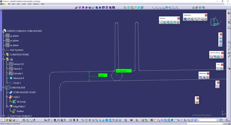
IMAGE SHOWING , DRAFT ANALYSIS OF THE RIBS -