Week 8 - Challenge 1 - Draft Analysis on a Fan Cover
TOOLING AXIS FOR THE GIVEN FAN COVER
INTRODUCTION
Tooling axis is the direction in which the mould opens or the core cavity opens. By providing tooling axis to the component we can also do the draft analysis of the component. Draft analysis is performed on components where the ejection of materials happen after the material is made inside the tools.
OBJECTIVE
To create the tooling axis for the given Fan cover model meeting the requirements of the draft angle and perform the Draft analysis on the model.
METHODOLOGY
Skin data would be provided to us by the styling team to us.
The first step is to check the continuity of the class A surface. This is to ensure that there is no gap between surfaces. If we find any then we should fix that first.
The second step is to find the tooling axis of the component.
DESCRIPTION
DRAFT ANALYSIS-
Parts cannot be ejected from the tool if they have a straight 90° profile from its base surface. This is because when the material is cooled the material tends to shrink and it would be difficult to remove the component from the tool. A small draft is provided on each and every area of the component for easy removal. Draft analysis technique is used to analyse whether our part model created in cad is manufacturable based on the draft condition applied.
Here we are also providing a direction in which the material should eject in order to get an easy removal of the component from the tool. It also lets us know whether a component is having a draft angle and hoe much draft angle from the tool direction.
For the Draft analysis we would need a tooling axis. Tooling axis is the direction in which the mould opens or the core cavity opens.
The first step is to check the continuity of the class A surface. This is to ensure that there is no gap between surfaces. If we find any then we should fix that first.
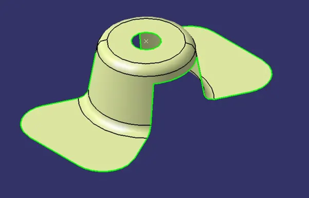
The second step is to find the tooling axis of the component. We try to find the best tooling direction visually. When we check in at X and Y direction, because of the hole we will to add a separate side core which in turn would increase the cost of production. As an engineer our aim should also be to reduce the cost. Z direction is a suitable direction since it will clear the hole as well as the slot.
After selecting the direction we have to create an axis which will be the tooling axis.
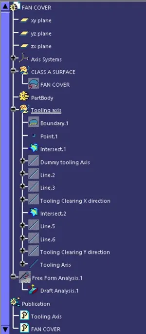
We create an axis along the z axis as a dummy axis for reference.
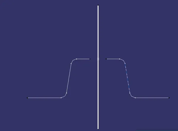
We then use the bisecting method to create the tooling axis. We can do it by bisecting the line we get at X direction and the line we get at Y direction and the resultant line would be the tooling axis.
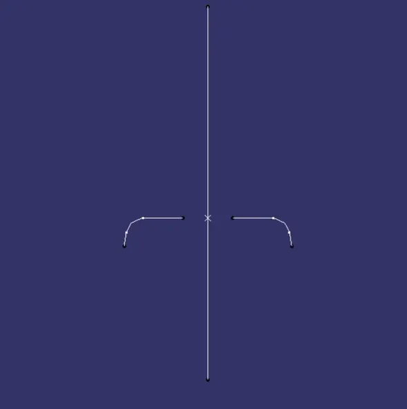
Line from X direction-
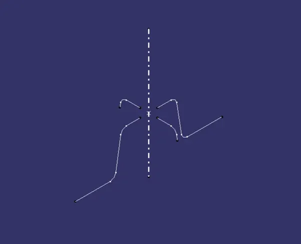
We use the intersection tool from the surface workbench to get the intersecting line by interesting the body and the ZY plane.
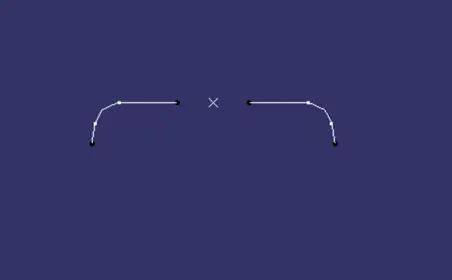
By referring the dummy tool axis we can select the face which are almost parallel to it on either side.
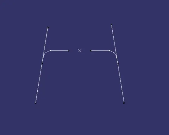
Then will creates a line using the line command tool and then will bisect the tool using the option in line command and we get the resultant line on ZY plane.
Line from Y direction-
We use the same technique like before.
We use the intersection tool from the surface workbench to get the intersecting line by interesting the body and the ZX plane.
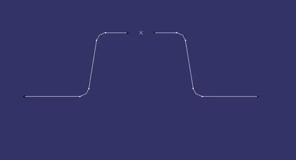
By referring the dummy tool axis we can select the face which are almost parallel to it on either side.
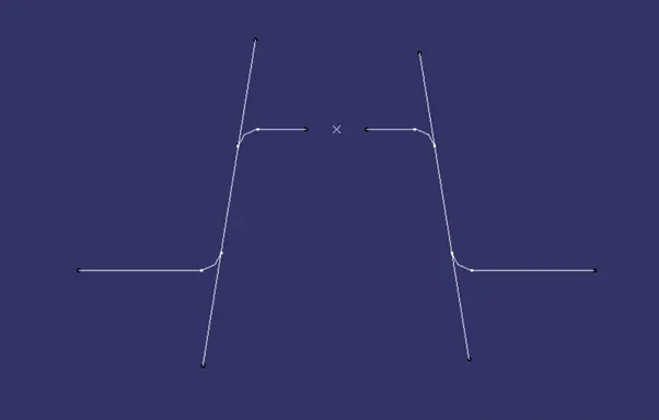
Then will creates a line using the line command tool and then will bisect the tool using the option in line command and we get the resultant line on ZX plane.
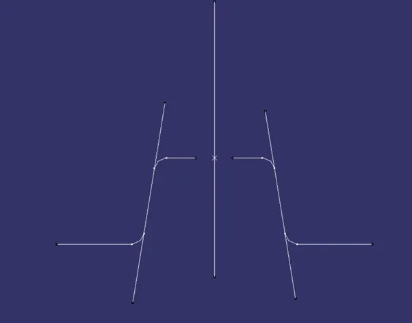
Resultant line-
Using the resultant lines which we got from the X and Y direction, we bisect the two lines and the result which we get would be the tooling axis of the component.
We select that tooling axis and publish it. This makes it easy it for us to search it in the tree.
Draft analysis-
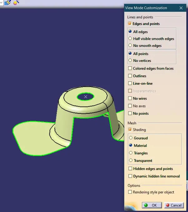
After creating a tool axis we do the draft analysis. Before drafting we have to make sure that in the view mode it is selected to the materials.
After selecting the feature draft analysis tool we drag the compass from its position to the tool axis. Then lock the compass. After that select anywhere on the component and it will give you the result.
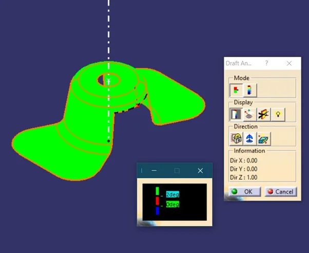
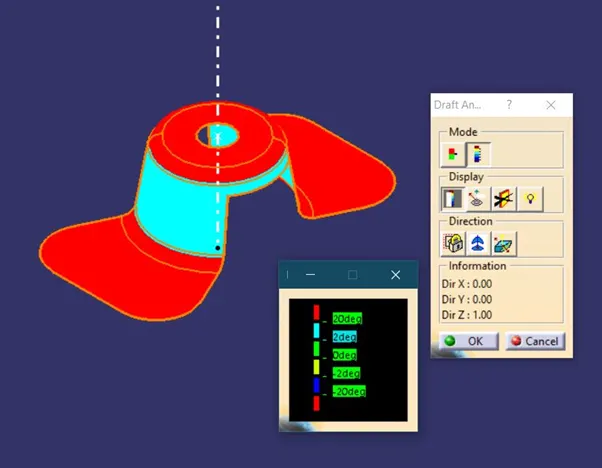
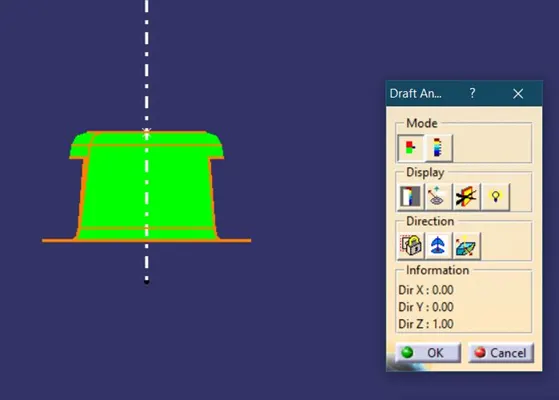
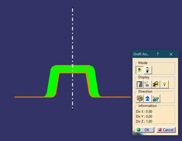
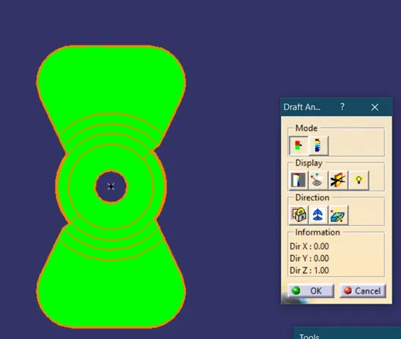
We can use the running point option to check the angle of the component.
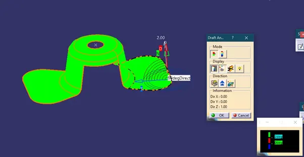
We can even modify the colour according to our preference.
CONCLUSION
With this we got to learn about the draft analysis option and how to create the tool axis for the draft analysis.