Week 8 - Challenge 1 - Draft Analysis on a Fan Cover
What is the draft?
it is defined as molded parts to make them easier to remove from molds.
there are two of determing the object to draft either by expiicitly selecting the object by selecting the netual element , which makes the application detect the approximate face to use.
major industries use the minimum draft angleis 3degrees.
procedure:
we have check the continuity of the given class A-Surface
check the tree directions(X,Y,Z)axis and finally , we decided which is the best possible direction to produce a mould . That direction of the axis is called the Dammy tooling axis.
A fan with several drafted surface that is orinted in part loction . that the draft analysis initially assume Z-axix direction
in the Z-axix direction the face are either posotive or negative draft . so the Zaxis we have taken as dummy toolingaxix we need to create a perfect tooling axis.
process:
Tooling axis:
is defined as the direction as the direction in which the mold opens or core cavity.
create an axis system on a point.
create an intersecting line on the ZX-plane and class -A.
Pulling direction:
the direction corresponding to the reference from which the draft face are defined.
Draft angle:
this is the angle that the draft face make with the pulling direction. this angle may be defined for each face.
Parting element:
this plane , face or surface cuts the part in two and each portion is drafted according to its prevoiusly defined direction.
Neutral element :
this element defines a netural curve on which the draft ed face will lie. this element will remain the same during the draft . the neutral element and parting element may be th same element.
Steps:
1. For checking the gaps present in shape , use join and boundary option.
2. use the join feature and select the fan cover. if there are any gaps, we will get lines on the model.
3. use boundary option to get lines at boundaries of the fan cover.
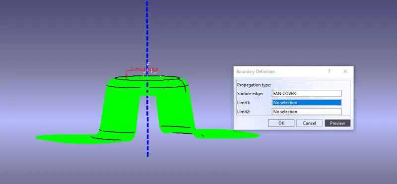
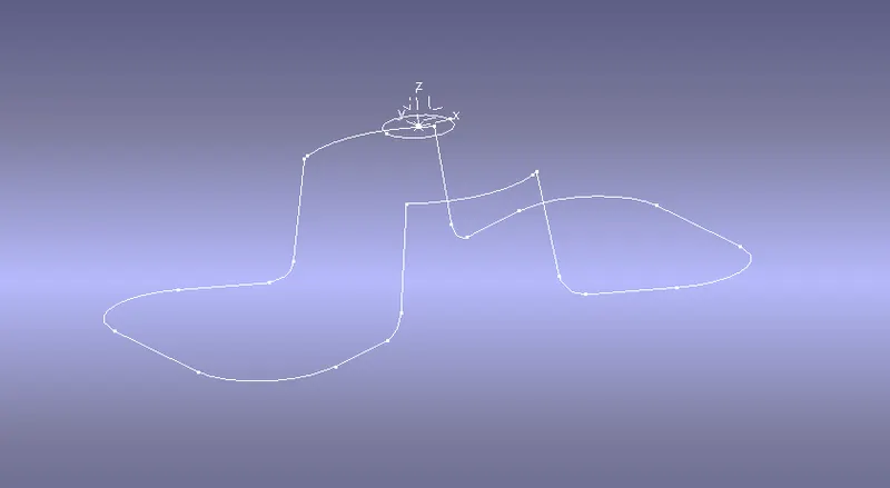
add axis system at Z- axis with a center point.
all dummy tooling Y-axis at the center point.
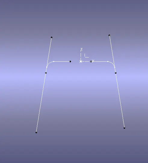
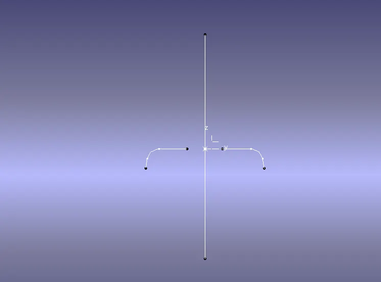
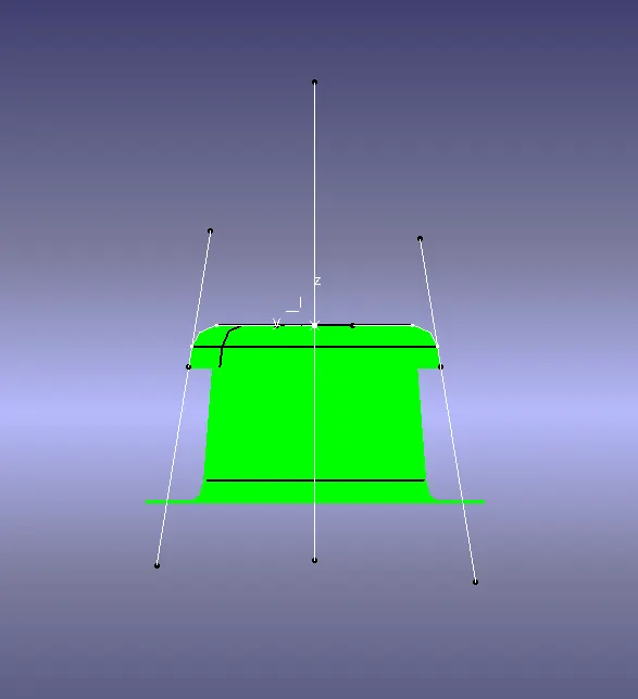
add axis system at Z- axis with a center point.
all dummy tooling X-axis at the center point.
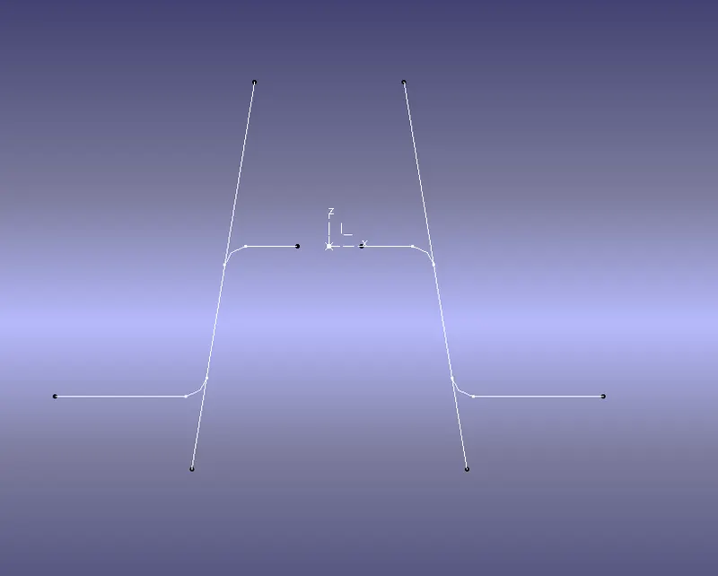
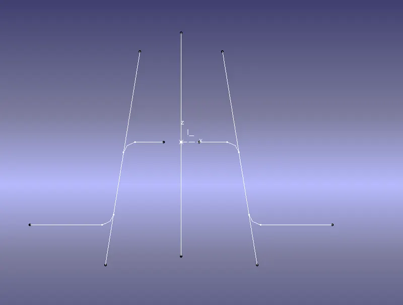
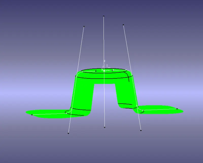
Draw a bi-secting line using X and Y axis . The below direction axix is the tooling axis and change graphical propertoes.
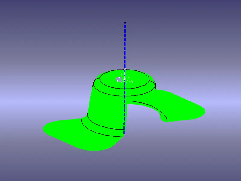
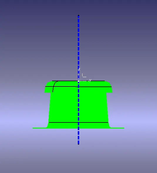
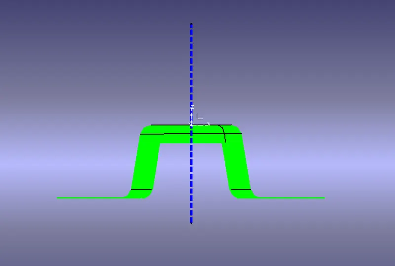
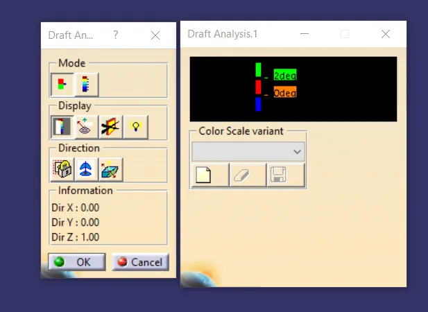
after selecting draft analysis , we get these two dialouges boxes. in the first row , two modes are displayed.
the second row is display and the third is direction.
using modes we can use drafting angle at a different minium and maximum angle.
the display is done using background light and analysis.
in the direction , w use the direction axis and lock it.
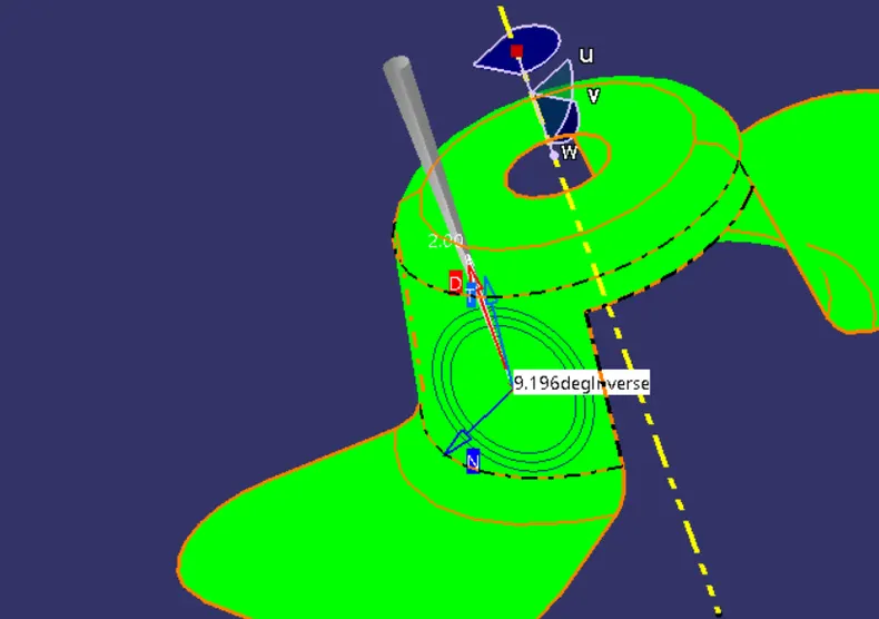
adjust the axis system using the direction 2nd optin. after adding an axis , do an analysis at each and every direction on the model . As shown below the analysis is done on the fan cover. the below are done when the draft angle are at 3 deg.
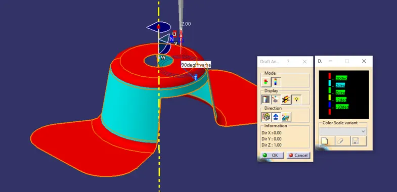
when we change mode , the analysis is done at draft angles-20 to 20 deg
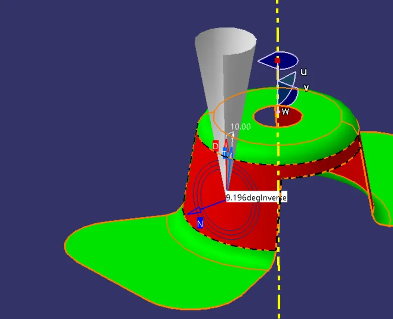
the below are formed when the minium draft angle is given as 3 degrees.
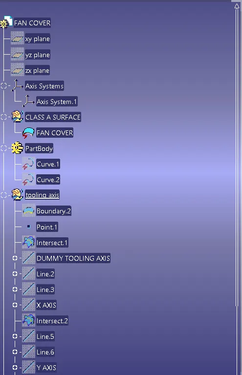
tree.