Draft Analysis on a Fan Cover using CATIA V5
AIM :
To create the tooling axis for the given Fan cover model meeting the requirements of the draft angle and perform the Draft analysis on the model.
THEORY :
Draft analysis is a method of checking the draft angle on various faces of a part with a particular direction.Every part like sheet metal parts which are generated from a Press Tool or some forming tools, may be the plastic parts which generally come out from the plastic moulds and maybe the casting parts, all such kind of parts required some drafted face on the surfaces which are parallel to the tooling direction. If we don't provide drafts on the surface then it will stick to the mould surface and whenever the mould is in motion they will destroy the surfaces or also reduced the finishing of surfaces.
PROCEDURE :
First we have to check the connectivity of Class-A surface.for that we use JOIN option to check how well it is connected,with the joint option once after selcting the component it will let us know if there are any surface gaps in the class A surface.
the other way to check the connectivity of the surface is by using BOUNDARY option. with the boundary as a tool,once after we select the component it will create a singe boundary set in the borders of class A which is higlighted in green as shown below,this kind of boundary forms only when there is no discontinuties or gaps on the surface.
otherwise it will create discontinued borders around the parameters of class A surface.So if the surace is properly joined it will create a single boundary which includes the free all the crossectional edges.
later we diassemble the single boundary into no of actual boundary objects .
TOOLING AXIS :
Now the main concept begins which is finding the tooling axis for the component.Tooling axis defines the mold or core and cavity opening direction. we should create a tooling axis in such a way so that it should cover most of features,holes,geometries and most of the crossectional area.
we will check now the best suitable tooling axis direction through visual inspection of the model with naked eye along all the three axis directions X,Y and Z.
in the y direction ie., parallel to screen we can cover the faces which we are seeing with the y direction tooling axis but if we observe the surface there we are having a hole in the top side,which cannot be created with y directional tooling, same as for the x direction too we cannot create a hole with x axis as a tooling direction so from the above observations we can conclude that the hole and all the faces of the component can be covered with Z direction tooling axis.
now the next step is to proceed with the creation of tooling axis in the z direction.making sure that we are creating in seperate geometrical set by renaming it as TOOLING AXIS CONSTRUCTION or as rename it as our wish but making sure it is created under seperate geometrical set to avoid confusion in tree structure and also to make it easily accessible so that we can manage the constructon if there is any change is needed in future developments
we follow bisectional method to create the tooling axis using the geometric structure of the class-A surface.
firstly we will intersect the component with XZ and ZY planes. So that we will get two lines for creating the middle line which is the bisection line.
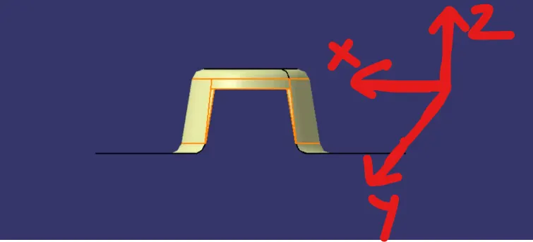
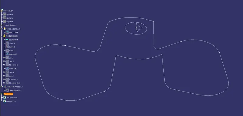
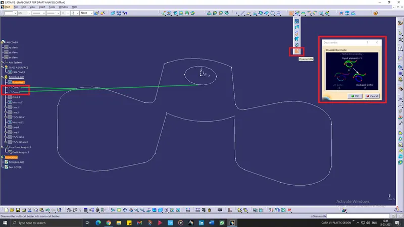
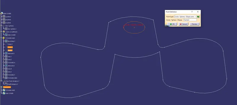
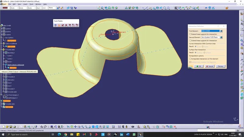
here we are creating line from point to point on both side of the faces.and with these two line we will create a bisecting line.we can select the direction of the tooling axis.and we name it according to the plane we have used to create the direction of line in this case we name it as "Tooling in X".
same as on the other side of the faces we will follow the same procudure but with different axis direction i.e., y direction.
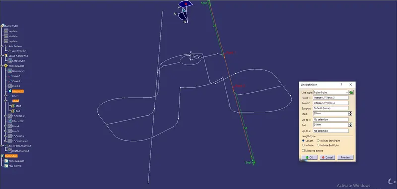
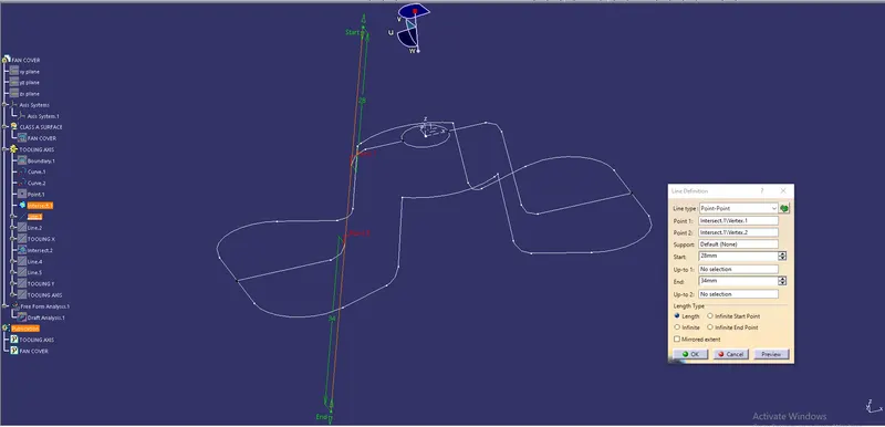
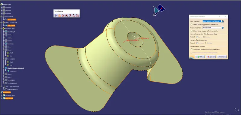
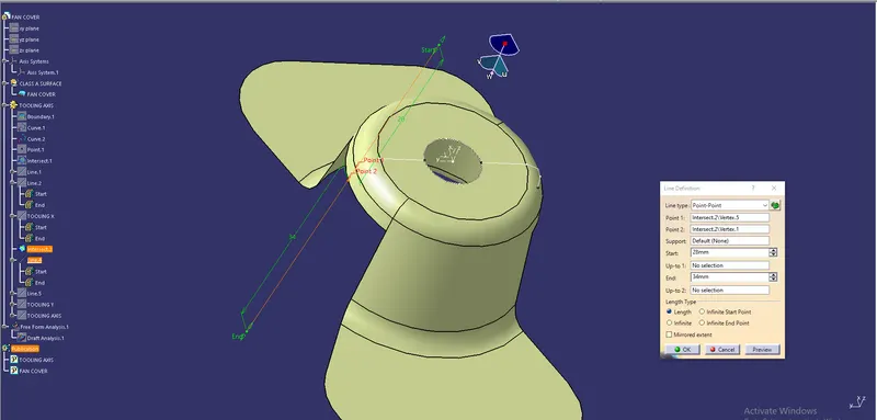
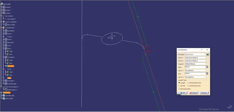
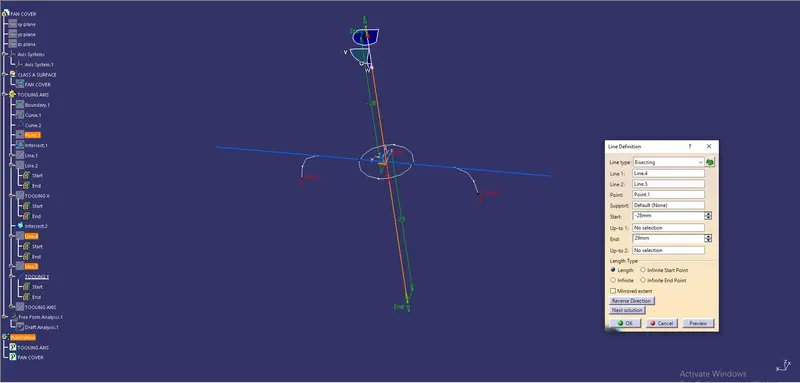
here we create a point in the middle for the purpose of bisecting the lines or tolling axis which are created in X and Y axis directions.with this bisection rule we are creating main tooling axis that should satisfy the drafting analysis.once after creating tooling axis we will higlight it by adding thickness and color to avoid confusion and publishing it for easier access.
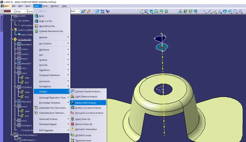
To access the draft analysis we will click on tools-analysis and select feature draft analysis which will redirects us to the draft tools with required tools like angle selection compass placement and color coding.
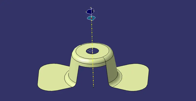
use the compass to define the new current draft direction. holding the red point in the centre of axis allows us to drag the compass in the axis which we have created earlier.from the image below we can see that the compass is inline with the tooling axis.
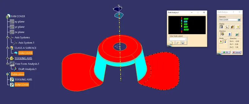
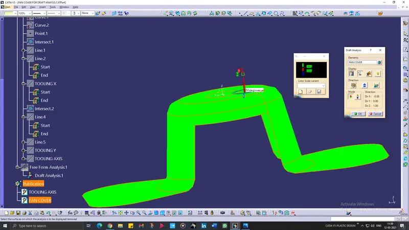
from the color coding above table it is said more than 2.9 is green and less than is red. when we lock the component and click on the running point it will show us a pointer which we can place it anywhere on the model so that it shows the angle w.r.t to the tooling axis.
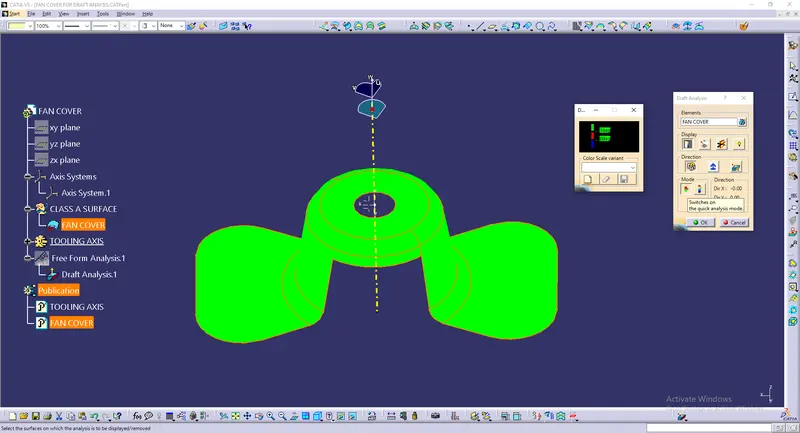
here the face is at 90 degree which means greater than the draft.
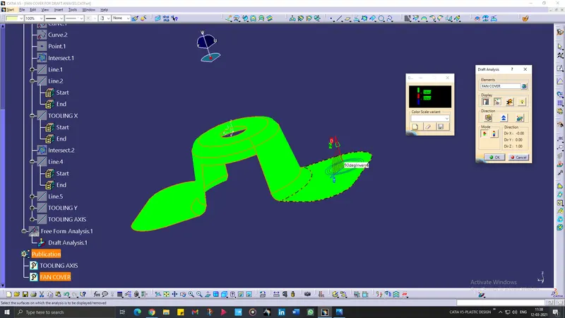
and here the side face measures the angle of 9 degree which satisfies greater than 3 degree draft condition so it will come out easily from the mold.
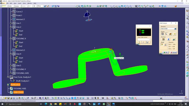
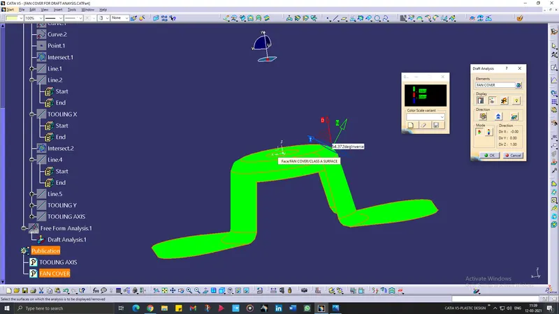
so the final image shows that the model is reaching the requirements of draft angle according to the given tooling direction,them we save the tooling axis and the draft analysis in the model and publish it for easier access.
RESULT :
Hence the tooling axis has been created for the given Fan cover model meeting the requirements of the draft angle and performed the Draft analysis on the model using CATIA V5.