Week 8 - Challenge 1 - Draft Analysis on a Fan Cover
DRAFT ANALYSIS ON FAN COVER
AIM: To create the tooling axis for the given Fan cover model meeting the requirements of the draft angle and perform the Draft analysis on the model.
tools used : point ,bisecting line .point to point line, extract intersect, boundary.
Procedure:
Creating tooling axis
- Open the given CAT part file.
- check for gaps between surfaces for that click on join and then preview
- extract the boundary and dissemble the boundary
- find the correct tooling axis where the material don’t interfere with the tooling axis and all the elements can be created
- create an axis system using at the centre of the fan cover
- Intersect the x plane and y planes with respect to the class a surface.
- Hide the class A surface and create point to point lines on the suspected drafts where the draft can interefere with the tooling axis.
- Create a bisecting line with the two lines and point to create a tooling axis of x plane
- Follow the above step for Y plane and assign these to different geometric set.
- Now create a bisecting line for the two bisections from plane X and Y in the direction of Z
- The tooling axis is created for the component
- make it thicker and give it color for identification and assign it to a geometric set.
DRAFT
Drafts are defined on molded parts to make them easier to remove from molds
The characteristic elements are
Pulling direction: This direction corresponds to the reference from which the draft faces are defined
Draft angle. This is the angle that the draft faces make with the pulling direction, This angle may be defined for each face. Parting element This plane face or surface cuts the part in two and each portion is drafted according to its previously defined direction
Neutral element: This element defines a neutral curve on which the drafted face will lie This element will remain the same during the draft. The neutral element and parting element may be the same element
DRAFT ANALYSIS
The Draft Analysis command enables you to detect if the part you drafted will be easily removed. This type of analysis is
performed based on color ranges identifying zones on the analyzed element where the deviation from the draft direction at any
point corresponds to specified values
TOOLING AXIS
The Definition tab on the Tool As dialog controls how you want the tool to orient itself whilst cutting a multi-axis toolpath Total as-Select to define the tool orientation. The default value is Vertical which is used for standard 3-axis machining How can be a fund larger continuously changing orientation.
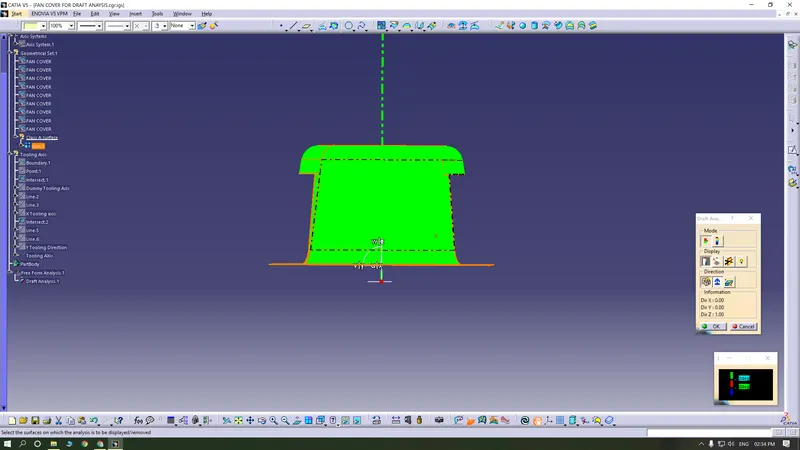
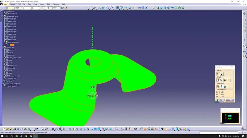
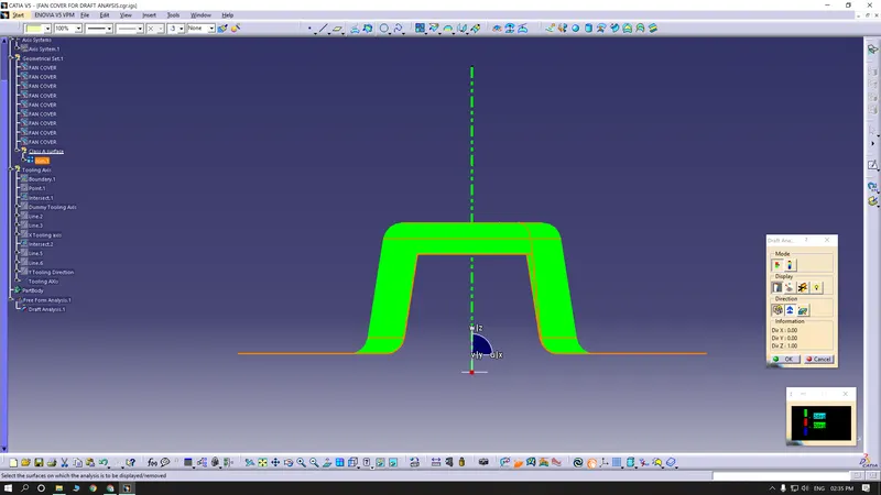
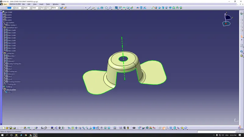
Result
The tooling axis for the given fan cover model is successfully created and draft analysis has also been performed for the same