Photo Realistic Rendering
AMERICAN CHOPPER MODELING AND PHOTO REALISTIC RENDERING
OBJECTIVE:
The objective of this project is to learn and understand the different tools and commands in SolidWorks
- To model different parts of a custom designed American chopper using SOLIDWORKS.
- To assemble the different parts modelled.
- To create a photo-realistic view of the American Chopper
- Rendering the model using SOLIDWORKS Photo view 360 and Solid works Visualize.
Parts Modelled for Chopper:
These are the following Parts of the Chopper, Modelled and assembled using SolidWorks.
- Transmission Belt
- Kick Stand
- Front Fender
- Rear Fender
- Oil Tank
- Chain
- Pedal
- Front Wheel
- Rear Wheel
- Front Fork
- Chassis
- Engine
- Gas Tank
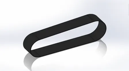
Transmission belt
The Transmission Belt is used to transmit the Power from Engine to Gear Box.
Features used
Sketch: The sketch is a two-dimensional representation of the model. The following are the entities available in solid works Line, Arc, Spline, Circles, Rectangle.
Offset: one or more sketch entities, selected model edges, or model faces by a specified distance
Extrude: Extrude is used to convert a 2D sketch into the 3D model.
Fillet: Fillet/Round creates a rounded internal or external face on the part. You can fillet all edges of a face, selected sets of faces, selected edges, or edge loops
The procedure for Transmission Belt:
- The 2D sketch is created in the front plane by giving it dimensions, relations to fully define a sketch. While sketching, the offset command is used to duplicate the sketch to some distance.
- After this process, the sketch is closed. Then, the extrude command is used to convert a 2D sketch into a 3D model.
- Then, the fillet is given to the belt as per the requirements. The model of the transmission belt is created.
Kick Stand
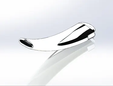
Kick stand is a supporting structure provided to a bicycle or motorcycle to help it stand in a vertical position when stationary. It is also known as side stand.
Features used
Loft: To generate complex geometry in a single feature.
Dome: Select one or more planar or non-planar faces. You can apply domes to faces whose centroid lies outside the face. This allows you to apply domes to irregularly shaped contours
Extrude cut: Extrude cut is another great feature which helps to remove material from the 3D model.
Split: The Split tool is used to project an entity (sketch, solid, surface, face, plane, or surface spline) onto other surfaces or curved/planar faces. You are also able to split faces on multiple bodies with one command.
Procedure of Kickstand:
- The 2D sketch is created in the front plane by giving it dimensions, relations to fully define a sketch. While sketching we used the spline and trim commands.
- There are two new planes created and the ellipse are drawn in the new plane as per the requirement.
- Then the loft command is used to create a loft for the Kickstand.
- The extrude cut command is used to cut the parts which are not required for the stand.
Front Fender:
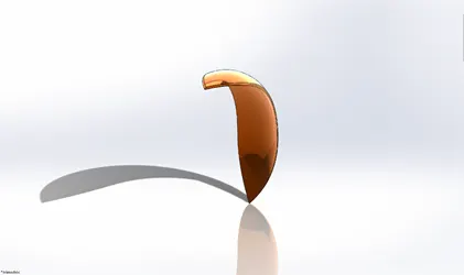
Front Fender is also called as mud guard. Its primary purpose is to prevent sand, mud, rocks, liquids, and other road spray from being thrown into the air by the rotating tire.
FEATURES USED:
- Revolved Boss
- Split
- Fillet
Procedure of Front Fender:
- A sketch of created in the front plane using a three-point arc and offset it meet the thickness of the fender. Create an axis at the origin.
- Using revolve boss the required front fender is created. Two different sketches are created in the top plane and the right plane to cut the front fender in to required shape.
- Fillets are created on the sharp edges of the fender. Desired appearance is applied to the fender.
Rear Fender:
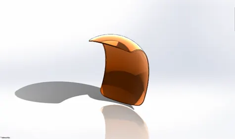
It is also called as mud Guard mounted on the chassis of the rear part above the Rear Wheel to protect the body from mud.
Features used
- Offset Entities
- Trim entities
- Revolve
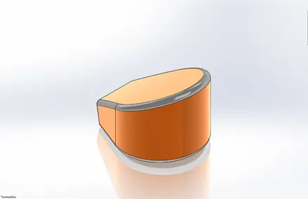
Oil-Tank:
Oil tank is used to store the oil for smooth running of engine.
FEATURES USED:
- Sketch
- Boss Extrude
- Combine
- Fillet
- Shell
Procedure of Oil Tank
- Using a 3-point arc and few lines and apply tangent relations. This to be done in top plane
- Extrude the profile to get a structure. Create another sketch and extrude it using mid plane extrude on front plane.
- Now split the bodies Apply necessary fillets.
- Now using shell feature make the oil tank hollow of required thickness
Chain:
It is responsible for transferring the mechanical power from the engine to the rear wheel of the bike.
Features used:
- Trim
- Fillet
- Blocks
- Extrude
- Patterns
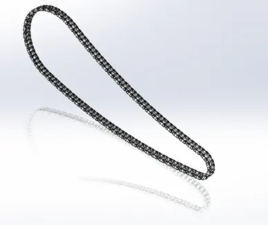
- A main profile of the chain is created using three-point arc and tangent relations between the arcs using the given dimensions. Create two throwaway sketches which are used to create the inside and outside links of the chain.
- The plates of the chain links are extruded using the throwaway sketches and the connecting pins are created using the same sketch. Only one side of the plates of the chain links are created.
- The Curve Driven Patterntool allows us to create patterns along a planar or 3D curve. We can base our pattern on an open curve, or a closed curve, like a circle. In the chain part Curve Driven Pattern is used.
- All the chain link plates are then mirrored on the front plain. All the components of the chain are combined as a single part using combine feature. Chrome steel appearance is applied to the chain.
Pedal:
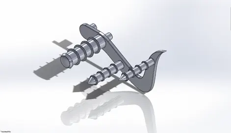
It is also called as Foot rest, It is mainly used for driver comfortness for easy shifting of gears.
Features used:
- Extrude
- Fillet
- Linear pattern
- Dome
- Chamfer
- Appearances
Procedure of pedal
- A sketch is made on the front plane in the form of the support plate as shown in the picture above.
- Building along the a few circles of required dimensions on either side of the profile which are later used to produce the extruded cylinders structures for foot rest and attachments to the chassis.
- Provide the required fillets and linear patterns to produce the ring structures on the pedal. And suitable appearance is provided
Front Wheel:
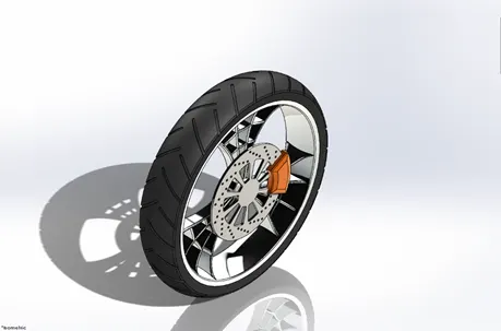
It is a circular component which controls the front and back motion of motorcycle. It consists of Rim, Tyre, Rotor, Sprocket and Calliper.
Features used
- Trim
- Revolve
- Fillet Entities
- Boss/Base Extrude
- Revolve Cut
- Linear pattern
- Chamfer
- Fillet Features
- Cut Extrude
- Circular Pattern
Procedure of Front Wheel
- A spider web design of the rim is created on the front plane and is extruded using mid plane extrude feature. And this spider web is circular patterned to required numbers and the Rim is completed.
- The spider web spokes and the rim are combined to form a single solid body.
- And Give suitable appearance for tire, rim, rotor, caliper.
Rear Wheel:
It is also a circular component which controls the front and back motion of motorcycle. It consists of Rim, Tyre, Rotor, Sprocket and Calliper.
Features used:
- Revolve
- Trim
- Fillet Entities
- Boss/Base Extrude
- Planes
- Revolve Cut
- Linear pattern
- Chamfer
- Fillet Features
- Cut Extrude
- Circular Pattern
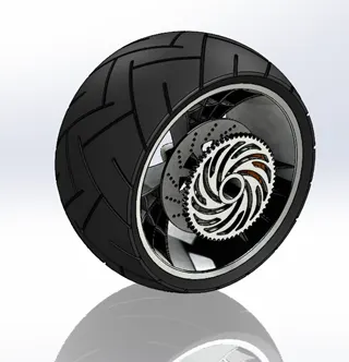
Procedure of Rear Wheel
- It is the same process as Front wheel.
- The disc and sprocket are attached with a rear wheel.
- The chain is connected between the Engine and the Rear Wheel. Chain is a positive drive. Compared to the belt it will be more efficient and losses in the chain drive are comparatively less.
Front Fork:
It is used to guide the entire vehicle. It holds the front wheel and other control device operated by rider. It consists of two columns along with shock absorber which is held together by triple clamp.
Features used
- Extrude
- Trim
- Revolve
- Split
- Plane
- Convert entities
- Move/copy Body
- Dome
- Mirror
- Combine
- Curve (Project Curve)
- Sweep
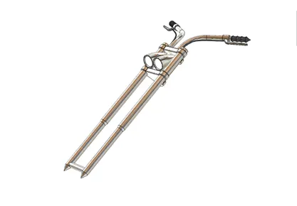
Procedure of Front fork
- Most motorcycles today usetelescopic forks for the front suspension.
- The forkscan be most easily understood as simply large hydraulic shock absorbers with internal coil springs.
- They allow the frontwheel to react to imperfections in the road while isolating the rest of the motorcycle from that motion. It filters the bums to give comfort to the rider.
Chassis:
It is the skeleton of the vehicle to which all the components of the motorcycle are attached to. It also provides the required support to the vehicle.
Features used
- Offset
- Convert entities
- Project Curve
- Trim
- Plane
- Sweep
- Split
- Revolve
- Cut Extrude
- Fillet
- Combine
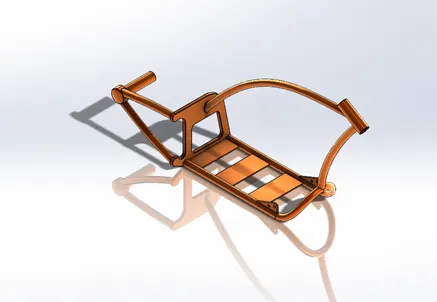
Procedure of chassis
- This chassis is made of 4 mm thickness tubes bent and joined using splines and created/projected curves.
- At the end all the tubes are connected to a plate and further this chassis is extended till the rear wheel hub.
Engine:
The engine is a component which converts a Chemical energy into the Heat energy and then the heat energy is converted into mechanical work by means of burning the fuel.
Features used
- Convert entities
- Trim
- Revolve
- Boss extrude
- Cut extrude
- Offset
- Dome
- Fillet
- Project curve
- Composite curve
- Sweep
- Mirror
- Circular Patter
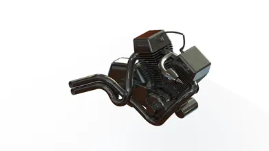
Procedure of Engine
Engine Consist of
- MOTOR,
- STARTER,
- PULLEYS,
- SPROCKET,
- ENGINE CYLINDER,
- AIR INTAKE MANIFOLD
- using the inserted picture and choosing the front plane, the base of the engine is created using three-point circle and lines (using tangency properties) and extrude to required dimensions.
- Again, using the same sketch extrude the two circles. Again, on the front plane create the twin engines in the V-shape.
- Create the sketch for pulley and create the pulley using revolved extrusion. Create the cylindrical part in the front of the engine on the front plane. Using the curves created and projected curves, create the profile of the exhaust pipes and create the swept boss feature.
- Then the spark plugs are created at the end. Apply the appropriate material to the engine.
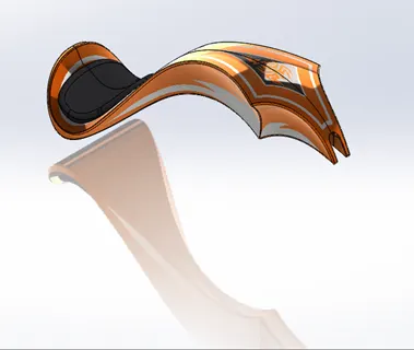
Fuel / Gas Tank
Gas tank is used to store the fuel gas. Fuel gas is required to drive the engine.
Features used to create the Gas Tank
- Trim
- Project curve
- Convert entities
- Sweep Surface
- Loft Surface
- Fill surface
- Surface trim
- Surface knit
- Sweep cut
- Fillet
Assembly of American Chopper components
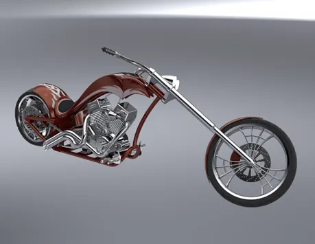
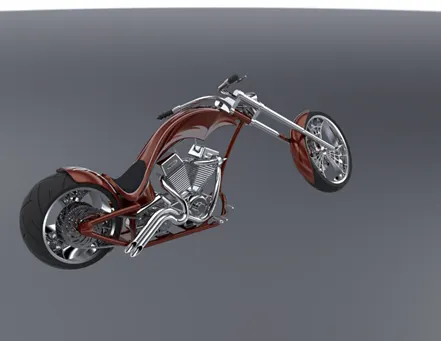
All the designed components are taken into the assembly section in Solid Works and using different mating features such as concentric, coincident, parallel, etc., the entire assembly of the American Chopper is created. After assembly the Decals are applied to the Chopper.
Rendering:
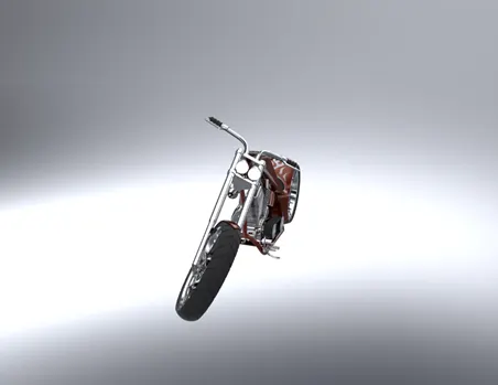
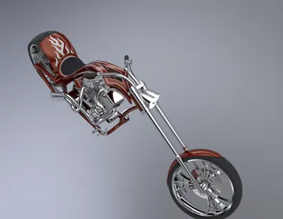
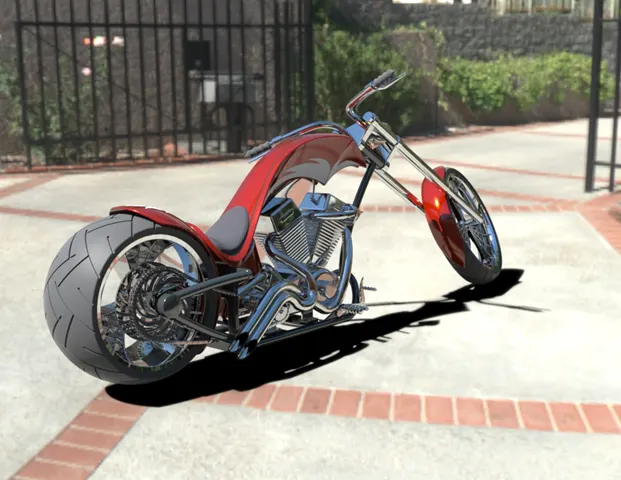
- Rendering is the process of creating realistic images of the Photorealistic model with the environment.
- Rendering has been done in two ways in SolidWorks. The following are the two ways,
- Photo view 360
- Solid works Visualize
- In the photorealistic model, some of the mate conditions and positions are changed to render realistic models.
- Then the photorealistic model is rendered into realistic images with different views.
CONCLUSION:
- The parts of the American Chopper are modelled.
- And all parts are Assembled and Rendered using Solid works2018 and Solid works visualise
Mentor: Mr.Soundar Rajan