Advanced Sheet Metal Design Using NX Cad Challenge_1_Casing Design
SHEETMETAL CASING DESIGN
OBJECTIVE:
- This report contains a detailed explanation of Sheet Metal Design of a Casing. The main objective of this course module is to learn the basics of Sheet Metal Design and also exploring most of the tools that are used in Sheet Metal Design using NX.
- To master the user interface and basic features of Sheet metal application in NX-12 like Tab, Flange, Break corner, Unbend, Creating holes, Rebind, Dimple, Bead, Mirror feature, and Flat pattern.
NX Sheet metal:-
NX software, the digital product development solution from Siemens, includes a set of state-of-the-art tools for designing sheet metal components. Using familiar terminology and workflows, NX Sheet Metal Design provides the design professional with a complete set of tools to efficiently create and manage sheet metal parts based on the knowledge of material properties and manufacturing processes. NX Sheet Metal Design tools incorporate material and bending information, enabling the model to represent both the formed component and flattened blank shapes.
The sheet metal design tools within NX allow companies to apply defaults – based on both industry and company best practices – to the values used in the creation of sheet metal parts. For example, bend radii and neutral factor values can be set to commonly used values to encourage re-use and save design time.
NX delivers a tailored environment for sheet metal design, with onscreen controls and modelling commands for typical features in sheet metal components.
NX Sheet Metal Design includes tools for unfolding bends to create accurate flat patterns for fabrication.
Benefits:
- Intuitive user interface results in the reduced learning curve
- Streamlined workflow requires less time for part design
Features:
Built-in design intent using a focused sheet metal workflow- Customer-defined default values
- Intuitive user interface
- Built-in intelligence for ripping and bend relief.
INTRODUCTION:
Sheet metal design is the process of making components from thin metal sheets by bending, cutting and fastening. Sheet metal design has varied application. The basics of sheet metal design are learnt and applied in creation of a Casing. The following steps were undertaking while designing the Sheet Metal Casing:
- Creation of the base plate
- Creation of bends, flanges and Break Corners
- Unbend the component
- Drilling holes
- Sketch the profile for the creation of the Dimple on the center Face
- Sketch and create Bead on the center face
- Rebend the Component
- Creation of the Draft.
DESIGN METHODOLOGY:
SHEET METAL CASING
 Base Plate Creation
Creating Bends
Creating Flanges and Break Corners
Unbending
Hole Drilling
Creation Dimple and Beads
Rebending
Drafting
FEAUTURES:
Sketches, Tab, Bend, Flange, Break Corner, Simple Screw Hole, Dimple, Bead, Unbend, Rebend, Flat Pattern and Drafting.
DESCRIPTION:
- SKETCHES: The Sketch is a 2D-dimensional representation of the model with the respect to plane/view.
- TAB: It is a base feature by extruding a sketch along a vector by a thickness value.
- BEND: This feature is used to bend the sheet by user defined line.
- FLANGE: This is a feature is used to create a flange from the stationary part by selecting a user defined edge.
- BREAK CORNER: This is a feature used to smooth the corner by selecting a Round or chamfer in option.
- SIMPLE SCREW HOLE: This feature is use to create a hole to any part with preferred type and specification of holes.
- DIMPLE: This feature is use to drop or lift the material through the sketch marking as a stamping feature.
- BEAD: This feature is also used to drop or lift the material along a counter of sketch that simulates staming a tool.
- UNBEND: This is a feature use to flatten the bend & flanges in a sheet metal part.
- REBEND: This feature is used to restore a flatten sheet metal part.
- FLAT PATTERN: This feature is used to create an instance of the flat shape and size of the sheet metal that required creating the final part.
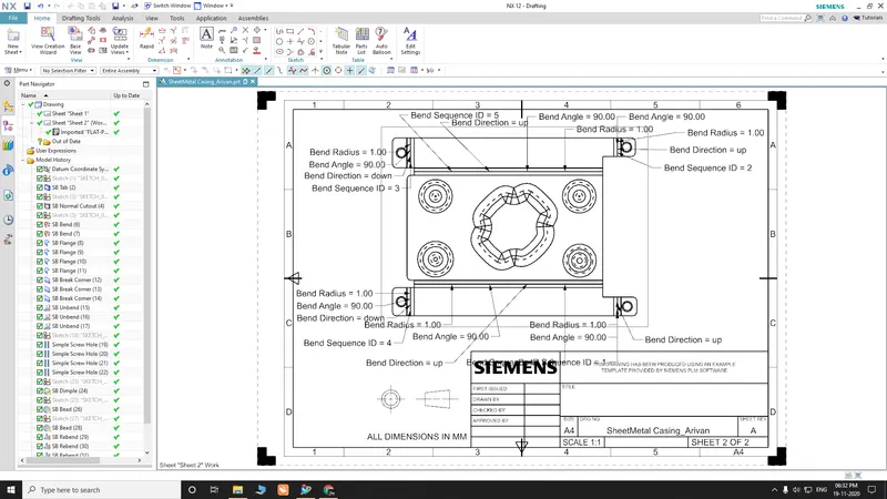
- DRAFTING: It is the creation of drawing for the purpose of determining what the dimensions of a part are.
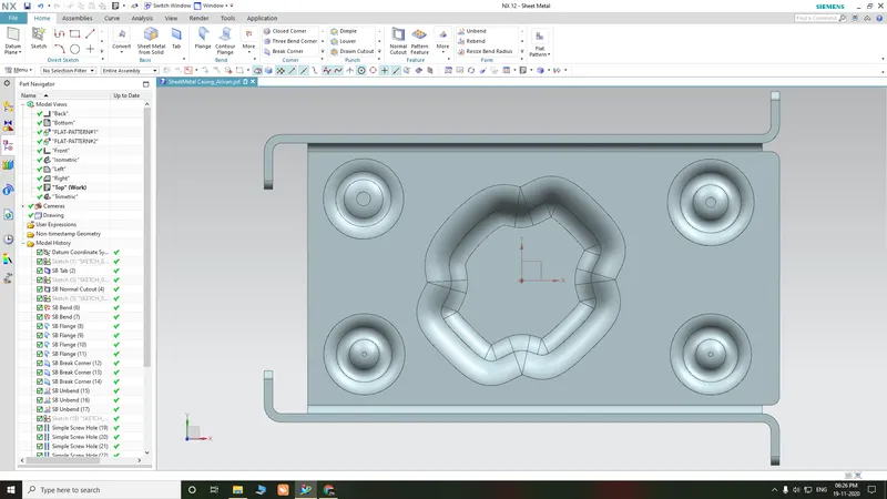
1.Top View
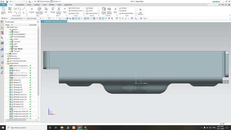
2.Front View
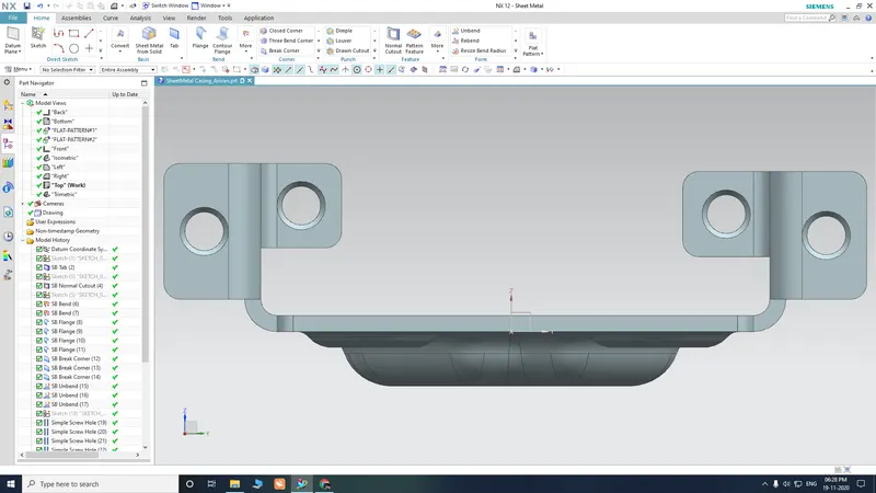
3.Side View
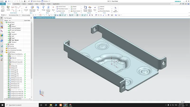
4.Isometric View
Drafting sheet
Conclusion:-
- Sheet metal casing is designed successfully in the NX-12 sheet metal environment.
- Basic Features of the sheet metal environment of NX-12 like creating a sketch, tab, flange, normal cut out, break corner, bend, unbend, Rebend, Dimple, bead, and the flat pattern are learned and applied in design.