Advanced Sheet Metal Design Using NX Cad Challenge_5_Odd Shaped Enclosure
Design of Odd Shaped Sheet Metal Enclosure
Objective:
The aim of this project is to create an Odd Shaped Enclosure using NX CAD Sheet Metal Application and create a detailed drawing for manufacturing.
Introduction:
- Sheet Metal Fabrication is the process of forming parts from a metal sheet by punching, cutting, stamping, and bending.
- Sheet metal is one of the fundamental forms used in metalworking and it can be cut and bent into a variety of shapes.
- Sheet metal is available in flat pieces or coiled strips.
- The coils are formed by running a continuous sheet of metal through a roll sitter.
Design Process Flowchart:
Sketch the shape
Construct the base features
Add features
Unbend and add advanced features
Rebend the sheet metal
Create a flat pattern
Design Process Flowchart:
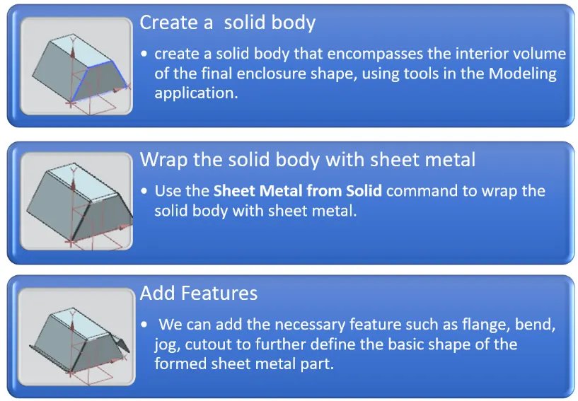
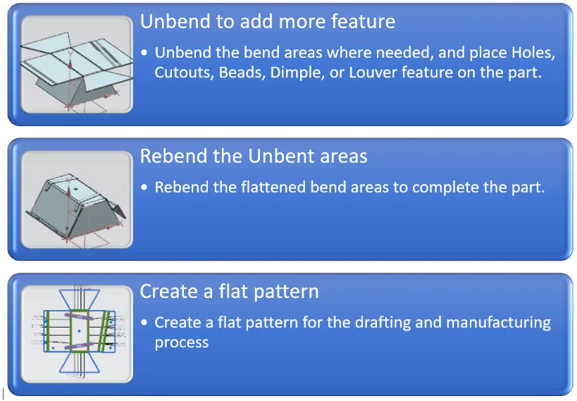
Description:
The software used to design this component is NX-CAD also called as Unigraphics. We are exploring the Sheet metal Module of NX CAD in this project. Some of the commonly used features through this modelling are explained as below.
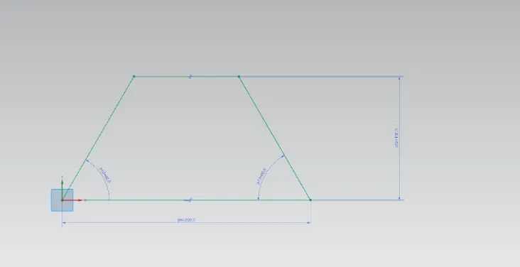
- Sketch - It is the basic of any design. This command is used the draw the shape of the design section
-
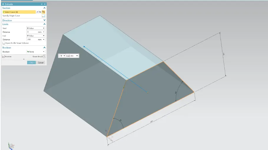
- Extrude - This command is used to create a feature by extruding a section along a vector. The shape of the section is created in sketch. It is created at the edge of one side of the model.
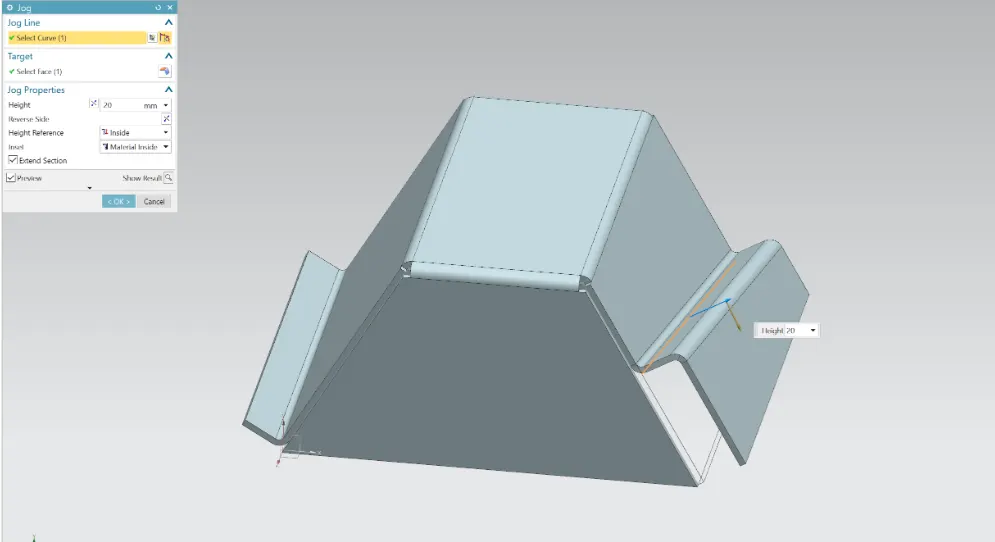
- JOG - This command is used to create an offset or a step in a tab. NX creates the jog by lifting the material on one side of the jog line and adding a flange between the two sides.
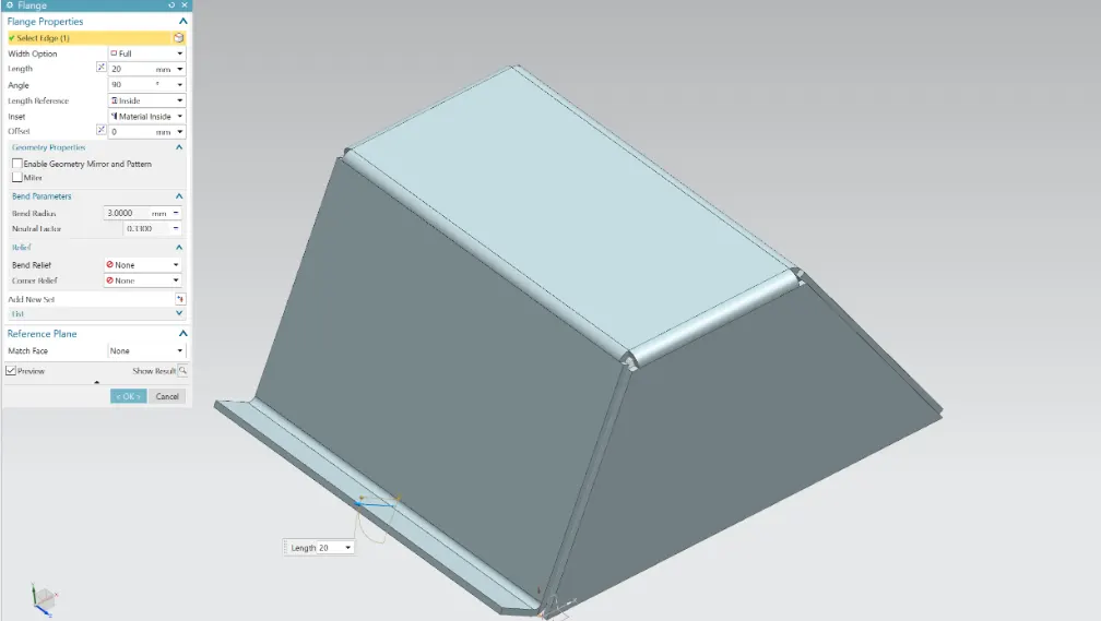
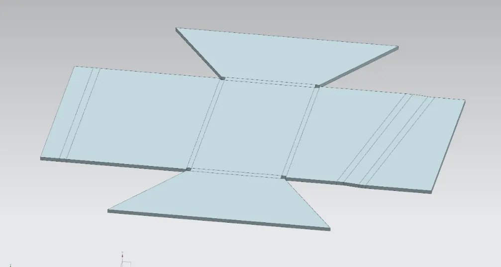
- UNBEND - This command was used to unbend the bent areas in the sheet metal to get the flattened sheet metal.
- HOLE - This command is used to create holes at desired location using points. This command is used to create six simple holes of diameter 10mm.
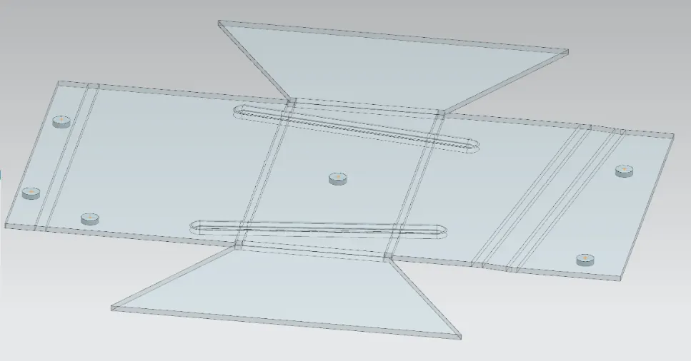
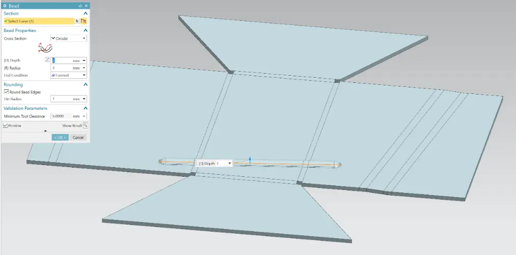
- BEAD - A bead is a long, drawn-out impression, which is impressed to increase stiffness in metal sheets or plates. This command is used to create two beads.
- REBEND - This command is used to rebend the unbent areas to obtain the bend features and also to obtain the final sheet metal part.
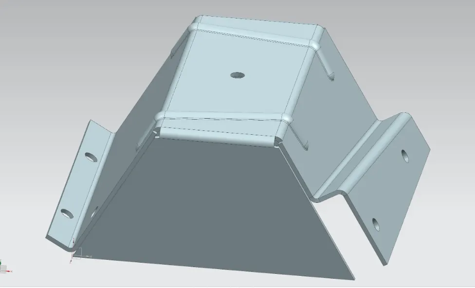
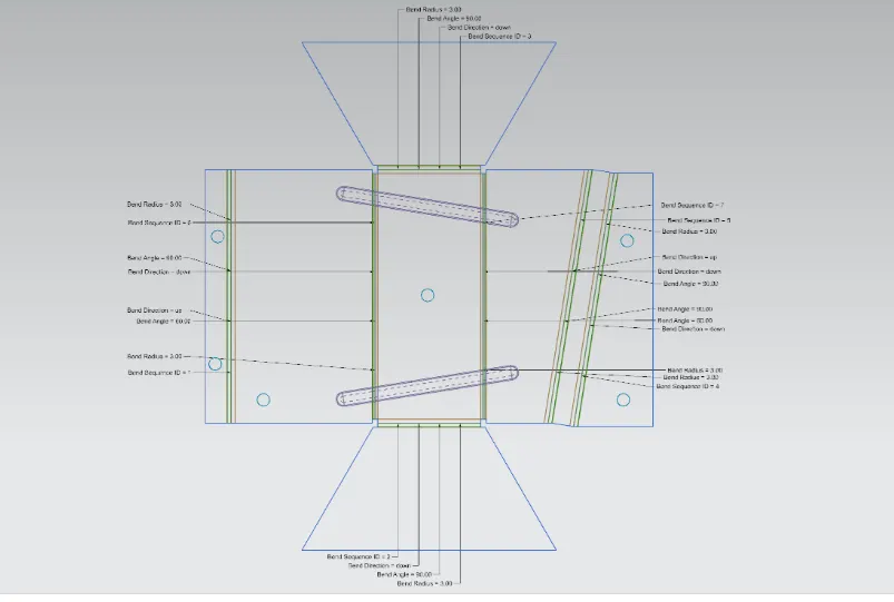
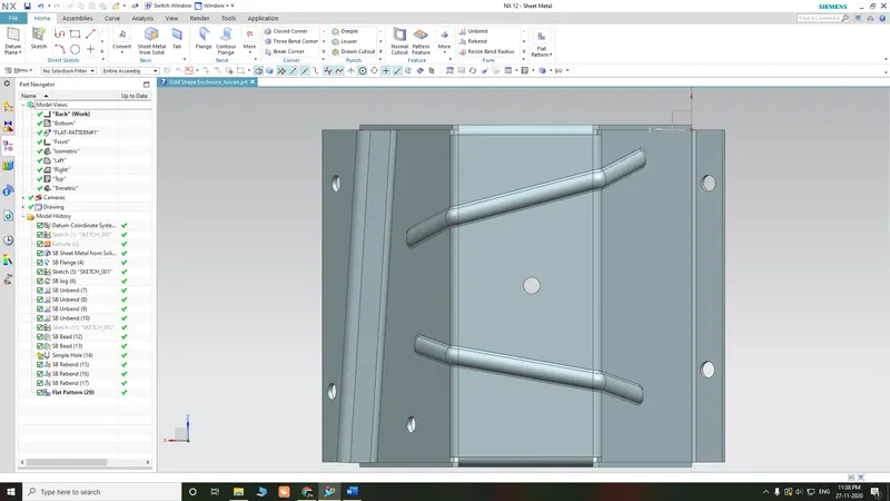
- FLAT PATTERN - This command to create the flat pattern view which is needed for drafting and later manufacturing purpose for a sheet metal. The user chooses this command to create a flat view of the sheet metal after unbending all the sides and faces.
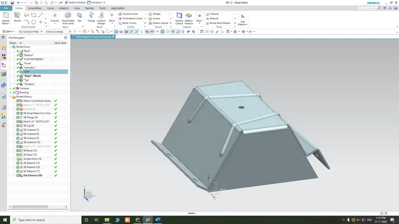
Some Views to Refer Feature Tree:
CONCLUSION:
Thus the objective of designing an Odd Shaped Enclosure in the NX CAD Sheet metal application is done successfully.
The proper utilization of the commands to get the desired output and also the flat pattern is achieved.
The final detailed drawing draft is also derived from the flat pattern.
These basic commands have influenced the designer to maintain geometric constraints and achieve the final product.