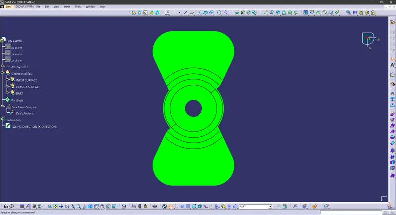
Week 8 - Challenge 1 - Draft Analysis on a Fan Cover
Aim: To Create the tooling axis for the given Fan cover model meeting the requirements of the draft angle and performing the draft analysis on the model.
Objective:
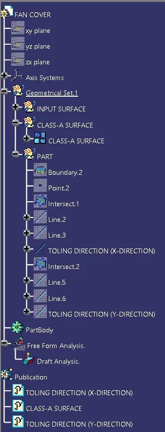
1. To ensure proper tree structure is followed.
2. Geometrical sets should have a proper name based on the sketches present inside of them.
3. All the sketches should be created under the geometrical set.
4. To publish the tooling axis and class-A surface.
Methodology:
Initially as an Input, we will be having a CLASS-A surface. Which will be designed by a Class A designer.
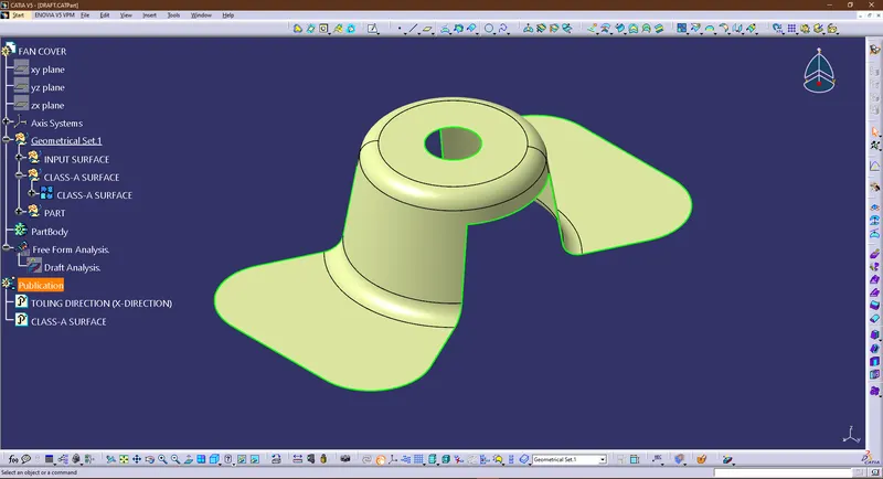
Tooling Direction:
Tooling Direction/Tooling Axis is an Direction which defines how the Plastic will be made. It defines some of the most important parameters.
1. what will be the orientation of the part.
Once this is done, a mould designer will be making Core and Cavity for the same part with respect to the main tooling direction.
Generally it is practiced to make the tooling direction Vertical/Normal to (90 degrees) the surface/face. Which is ideal condition.
Making Main Tooling Axis (bisecting method)
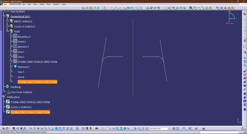
Next, we will be creating the tooling direction with Bisecting method, for that we will have too check for X and Y direction, since Z is the Main Tooling Direction we can make a bisector on Z axis.
For X we will be using the INTERSECT feature, and then create an Intersection and select Surface and the Plane which will give the following output.
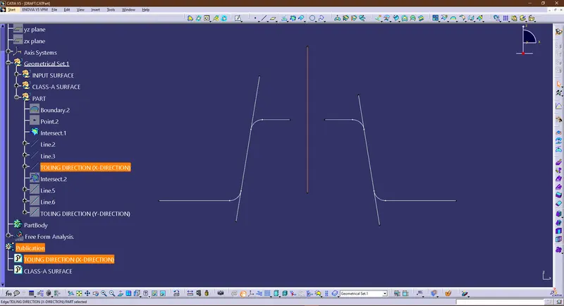
Then with the intersection we will make the lines using Point to Point method as shown. and using the bisect feature in line command. same will be follow for Y axis.
DRAFT ANALYSIS:
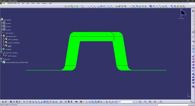
To perform Draft Analysis on the model. Go to menu bar > select insert > Analysis > Feature Draft Analysis To give the draft direction, use the compass and align Z-axis of it with the tooling axis which we created for the model. Once it is properly aligned, lock the draft direction. A red colour point will be shown on screen, select the fan cover (CLASS A SURFACE) and it will show us the current draft angle of the model. Set the draft value to 3 deg under the colour scale variant and press.
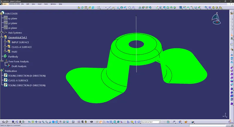
Using the Analysis option under Display Tab we can perform the draft analysis on the given model To publish the Tooling Axis and Class A surface (Fan cover).
first select it and then Go to menu bar > Tools Publication. This will publish the Tooling Axis and Class A surface which can be seen in the Tree structure PHRASES USED:
DRAFT Drafts are defined on molded parts to make them easier to remove from molds The characteristic elements are Pulling direction: This direction corresponds to the reference from which the draft faces are defined Draft angle. This is the angle that the draft faces make with the pulling direction, This angle may be defined for each face. Parting element This plane face or surface cuts the part in two and each portion is drafted according to its previously defined direction Neutral element: This element defines a neutral curve on which the drafted face will lie This element will remain the same during the draft. The neutral element and parting element may be the same element.
DRAFT ANALYSIS The Draft Analysis command enables you to detect if the part you drafted will be easily removed. This type of analysis is performed based on color ranges identifying zones on the analyzed element where the deviation from the draft direction at any point corresponds to specified values.
TREE
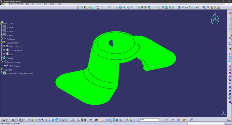
ISOMETRIC
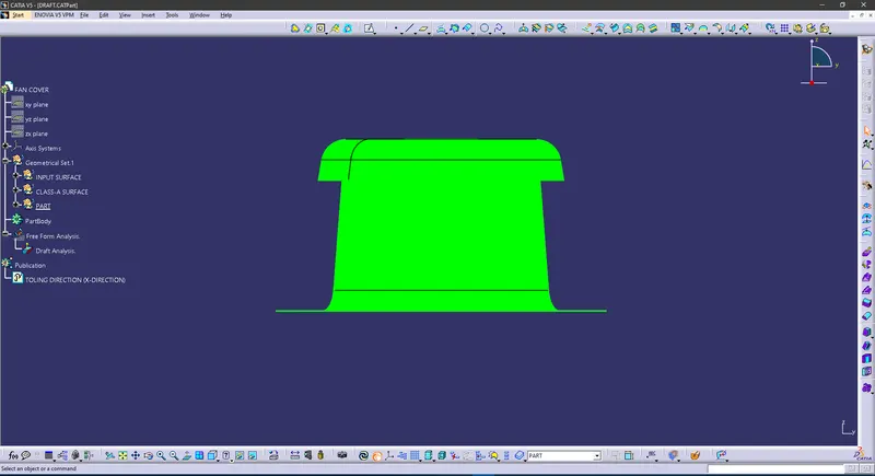
FRONT
SIDE
TOP