Week 8 - Challenge 1 - Base Bracket Design
BASE BRACKET
CLASS A SURFACE DRAFT ANALYSIS
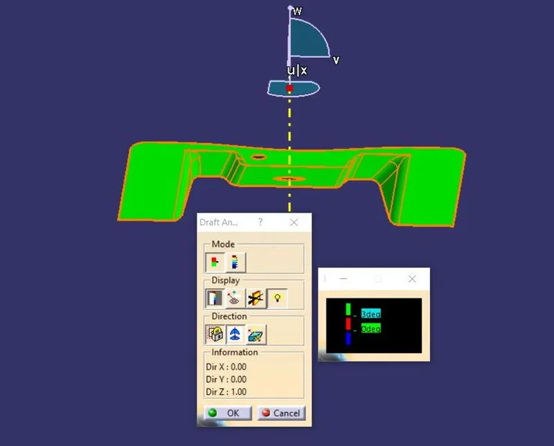
TOOLING AXIS:
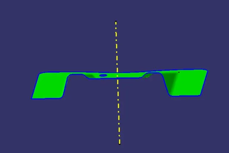
SURFACE B
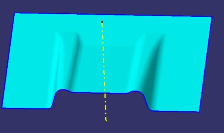
SURFACE C
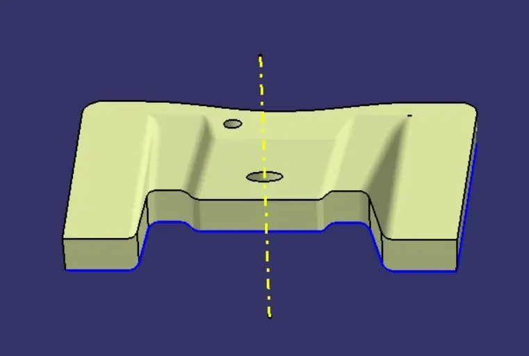
FINAL SURFACE
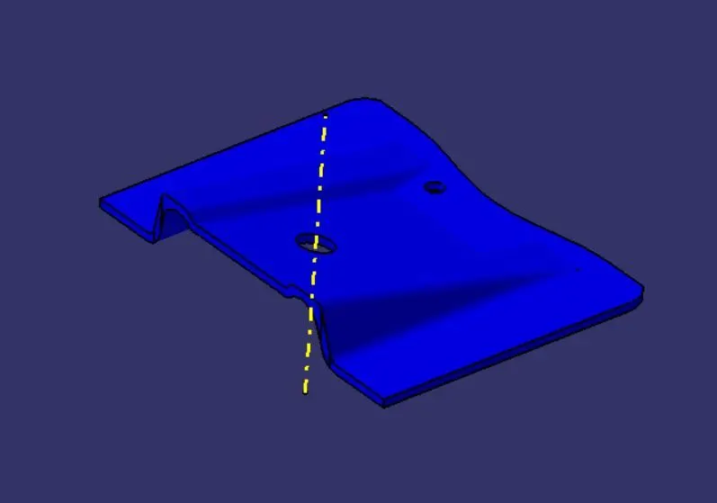
CLOSED SOLID BODY
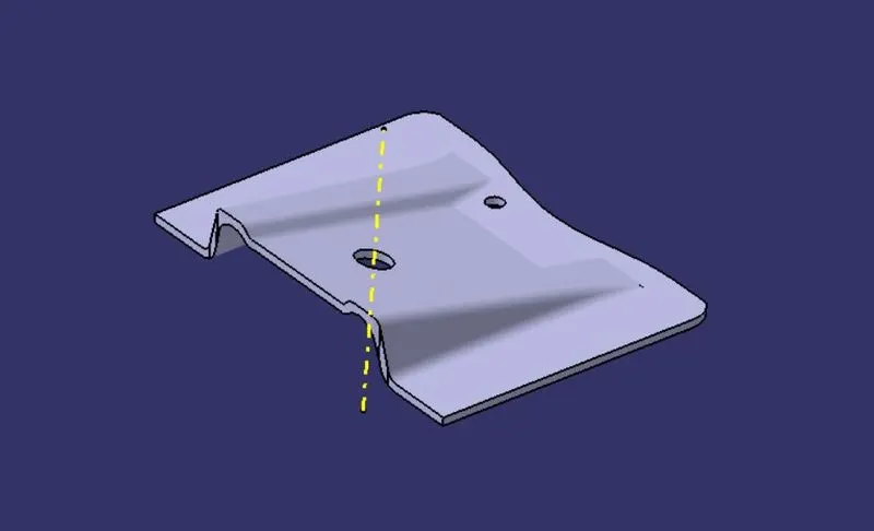
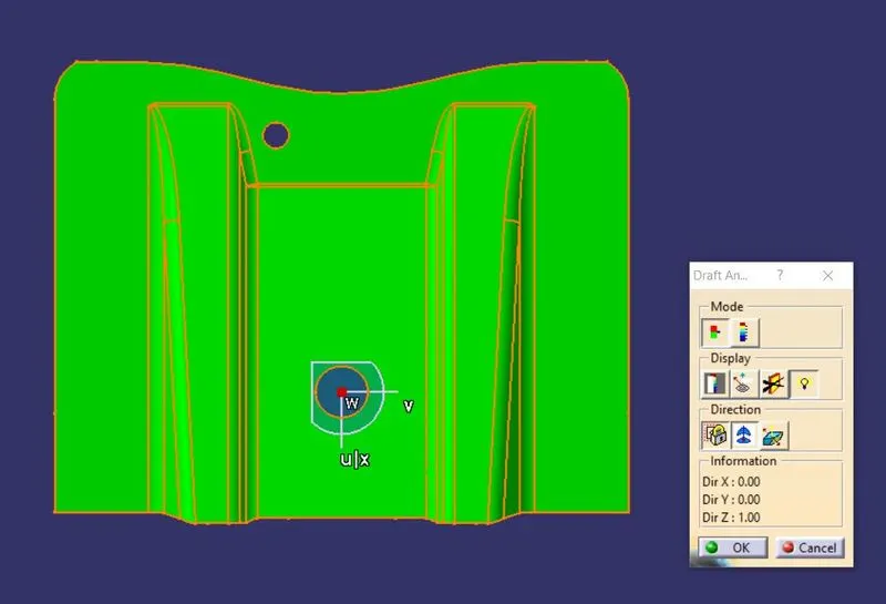
DRAFT ANALYSIS
The draft analysis technique is used to analysis whether our part model created in CAD is manufacturable based on the draft condition applied. Here the part should get easily removed from the panel dies ( incase of sheet metal part ) or mold (incase of plastic).
No parts can be ejected from the tool if it is having a straight 90-degreee profile from its base surface. A small draft angle is provided to each and every area of the component in order to get easy removal of the component from the tool.
step 1
Change the view mode to customize view parameters and select the material option from the mesh.
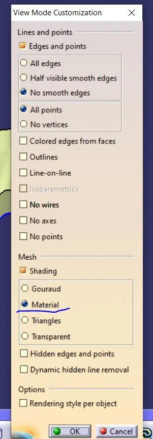
step 2
Draft analaysis option available inside the following workbenches:
- Part design
- Generative shape design
- Wireframe and surface for building
The draft analysis dialog box with colour scale appears on the screen. So the first mode option is the quick analysis mode and the second is the full analysisi mode. Here the quick analysis mode is used.
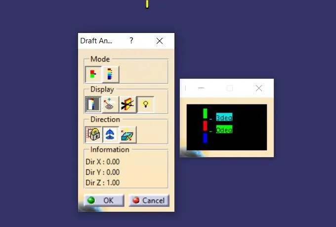
Change the value of green according to the draft angle provided to the part. Here the ideal draft angle is 3 degrees.
step 3
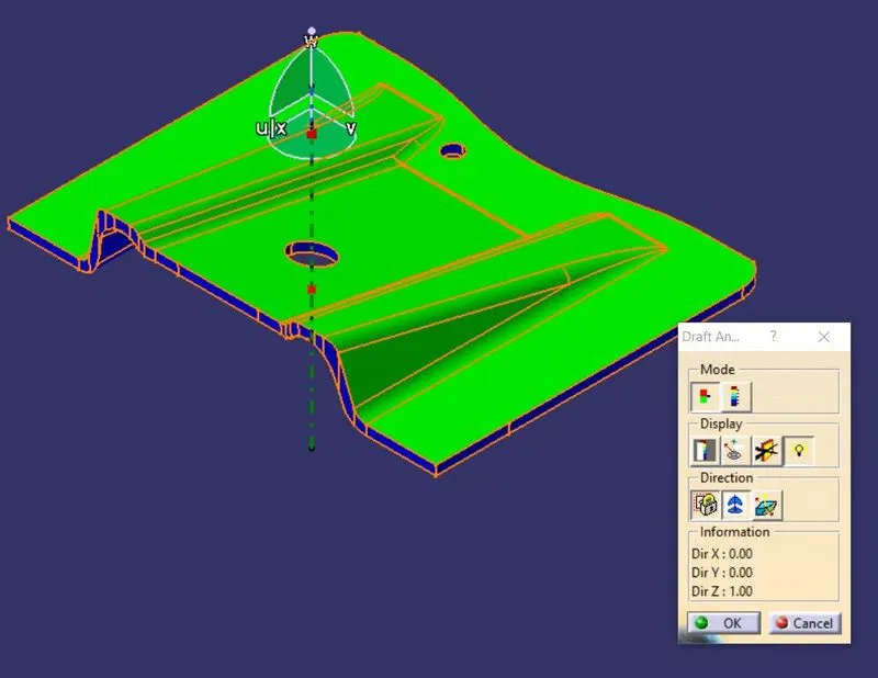
Drag the compass and place it over to the line.
step 4
After placing the compass ,click anywhere on the part.
ISOMETRIC VIEW
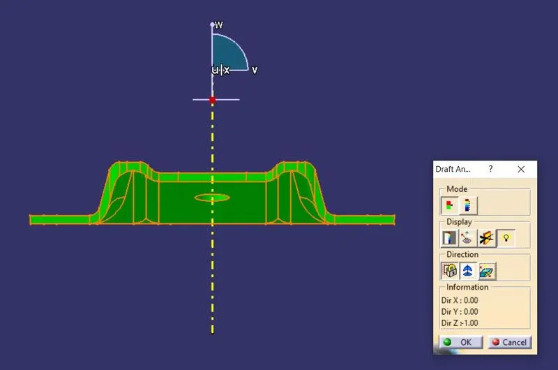
FRONT VIEW:
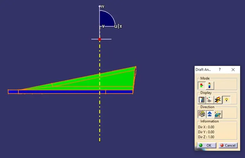
SIDE VIEW
TOP VIEW:
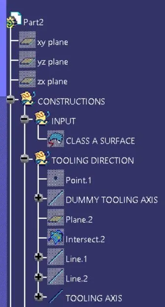
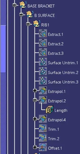
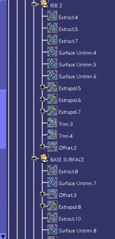
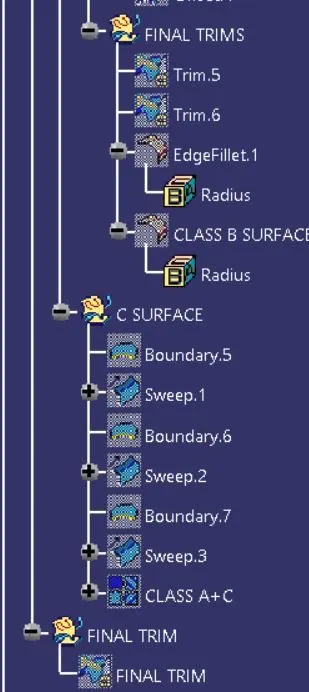
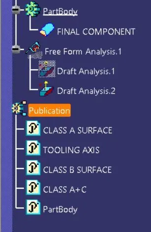
TREE STRUCTURE: