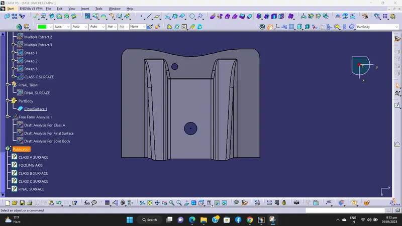
Week 8 - Challenge 1 - Base Bracket Design
BASE BRACKET DESIGN -
DESIGN PROCEDURE -
1) Class-A surface check.
2) Create tooling axis.
3) Draft analysis for Class-A surface.
4) Creation of Class-B surface.
5) Creation of Class-C surface.
6) Final trimmed surface.
7) Convert surface to solid.
1) Class-A surface check -
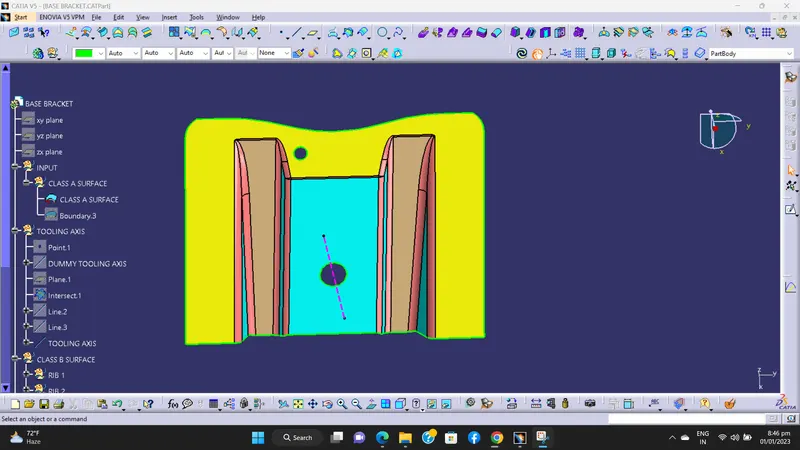
This surface is provided by styling team. Class-A surface is check by using boundary command, if there is any irregularity then it is clear by using join command.
Then published Class-A surface by using publication tool.
2) Create tooling axis -
Tooling axis is a line of direction where core and cavity will open.
In bisecting tooling axis method, analyze the model manually or visually to see which direction is most suitable for tooling axis.
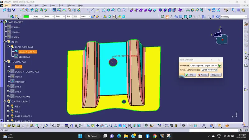
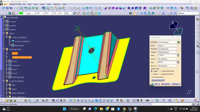
After checking all three direction we prefer Z direction, and creating a point at the centre of big hole.
Then through this point one line is drawn. Which our dummy tooling axis. This dummy tooling axis is help us for selecting X OR Y direction.
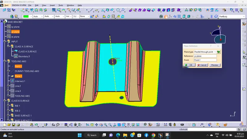
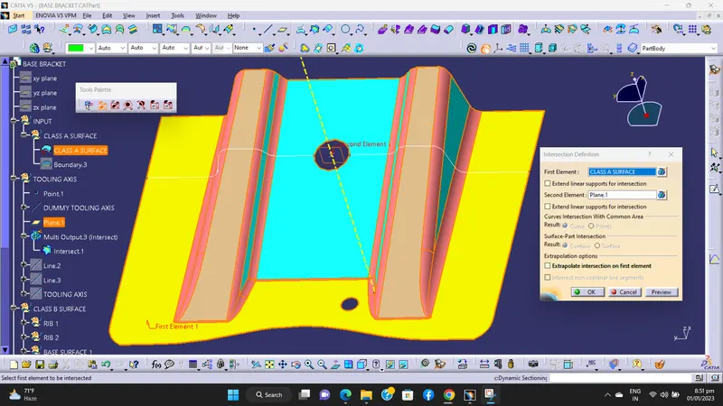
After that we creating YZ plane at that point. Through that plane the Class-A surface is intersect.
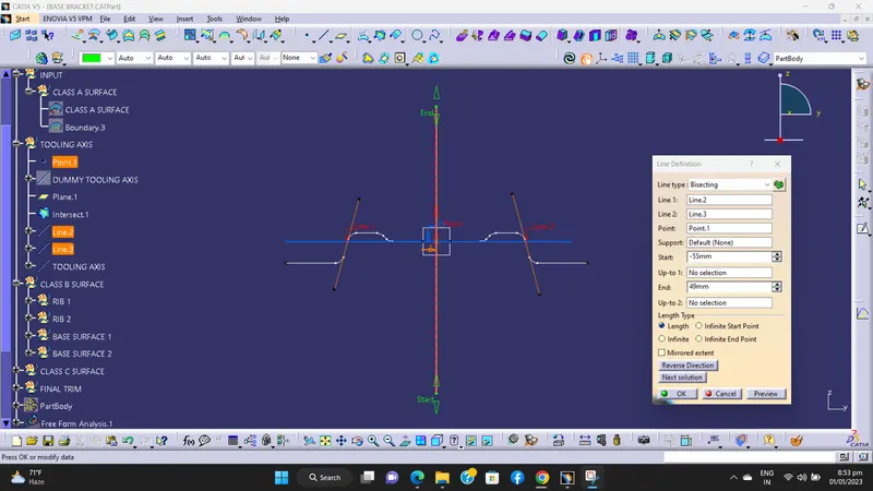
Then two lines are drawn to the side faces of the intersected curves. Then we create one more line by bisecting this two line. Which our tooling axis.
Then published tooling axis by using publication tool.
3) Draft analysis for Class-A surface -
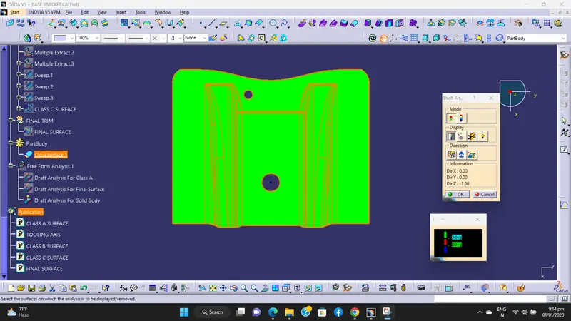
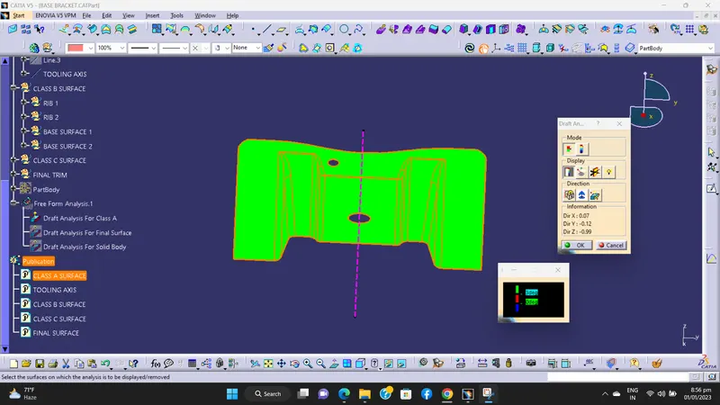
By changing the view mode to custom view, in the parameters – Material mode is selected. Then the feature of draft analysis is enabled.
Then the compass was activated and placed with the tooling axis by dragging the red pointer and then locked it.
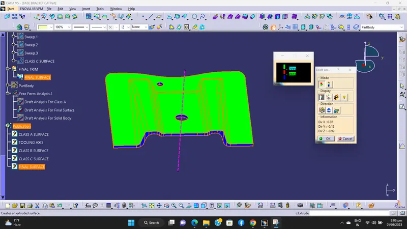
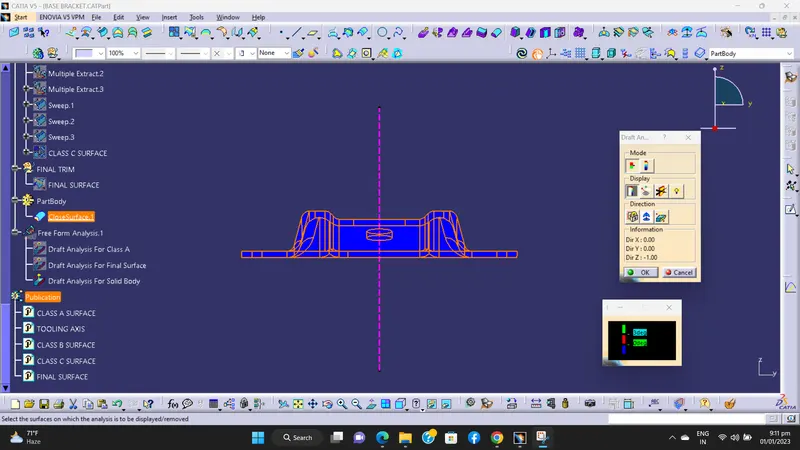
Then, by selecting the quick analysis mode, the nominal value will be 3 degrees and checked for the components draft angle.
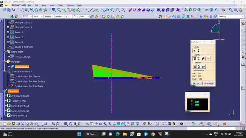
The green colour area shows that it satisfies the 3-degree draft angle.
If not satisfied then by using the running point tool the area is measured and then altered to get a successful draft for the created tooling direction.
4) Creation of Class-B surface -
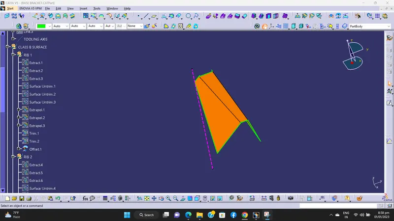
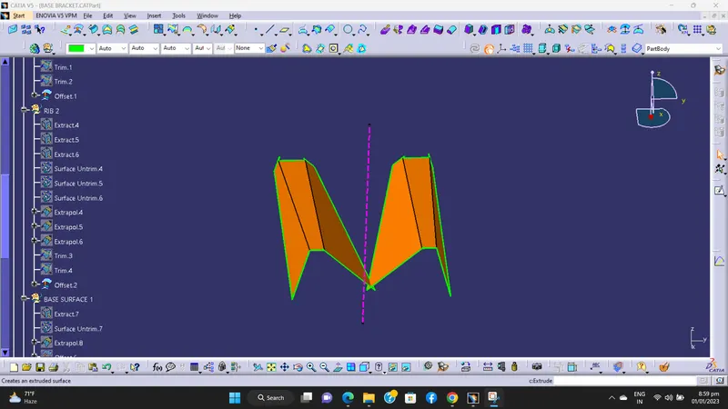
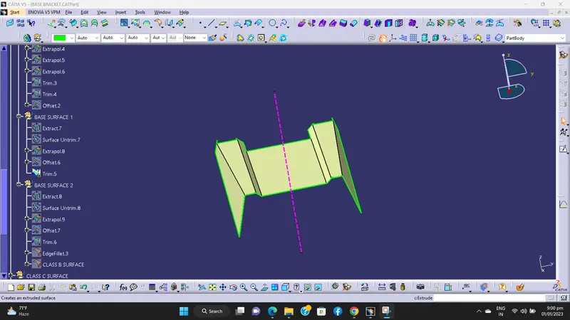
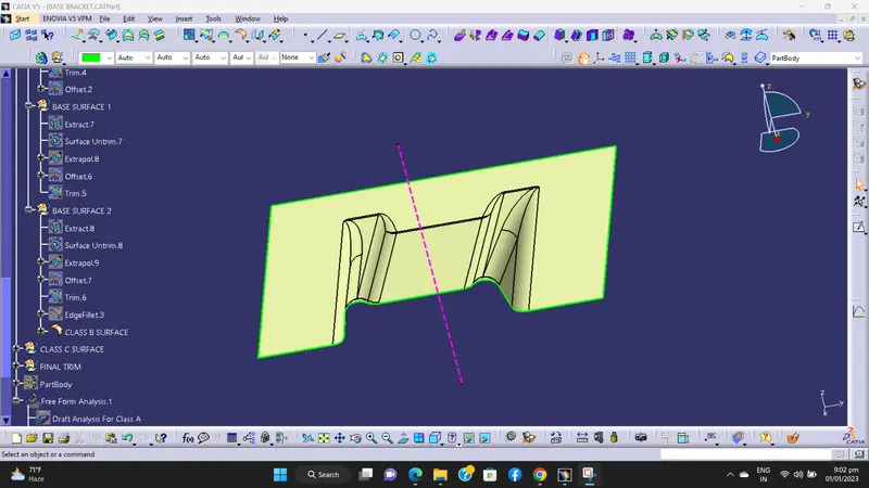
For creating the Class-B surface the required surfaces from Class-A surface have been extracted and then untrimmed all the surface.
Then all the surfaces have been extrapolated to get intersections between them.
Since the thickness of the Base Braket is 2.5mm the B-Surface was offset to 2.5 mm and the required trim operations must be carried out.
Finally, the required corners have been filleted by 5.5mm (3mm + 2.5mm)
Then published Class-B surface by using publication tool.
A) RIB 1 -
B) RIB 2 -
C) BASE SURFACE 1 -
D) BASE SURFACE 2 ( Class-B Surface) -
5) Creation of Class-C surface -
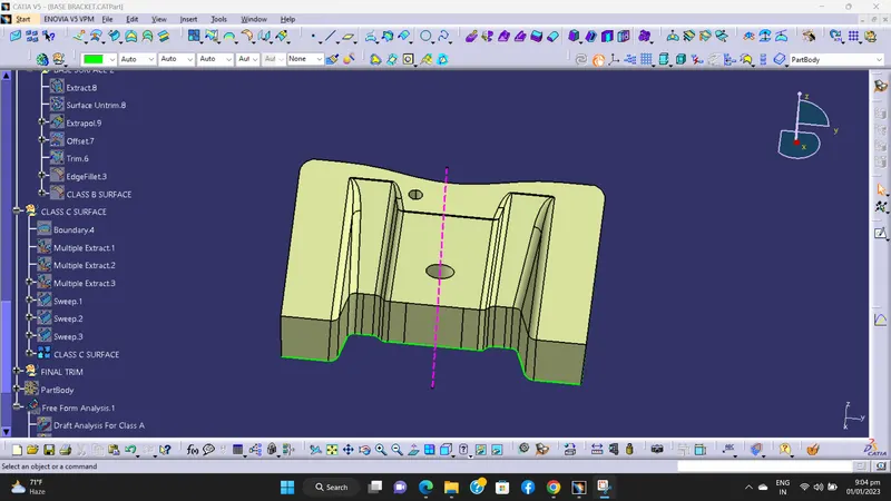
The required outer edges of the A-Surface were extracted using Multiple Extract.
Then by using the sweep command the surface was created.
Now the Class–A surface is join with the surface which created by using sweep command. So get our Class- C surface.
After that we published Class-C surface by using publication tool.
6) Final trimmed surface -
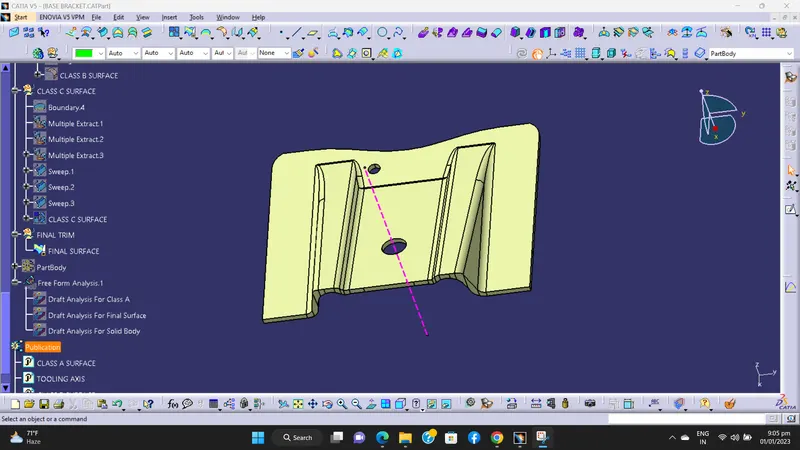
Now the Class–C surface trimmed with Class-B surfaces.
We got required final trimmed surface.
Then published final trimmed surface by using publication tool.
Draft analysis for final trimmed surface.
7) Convert surface to solid -
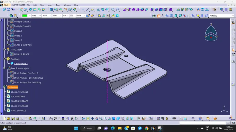
Now in part design workbench the final trimmed surface is converted into solid part by using close surface command.
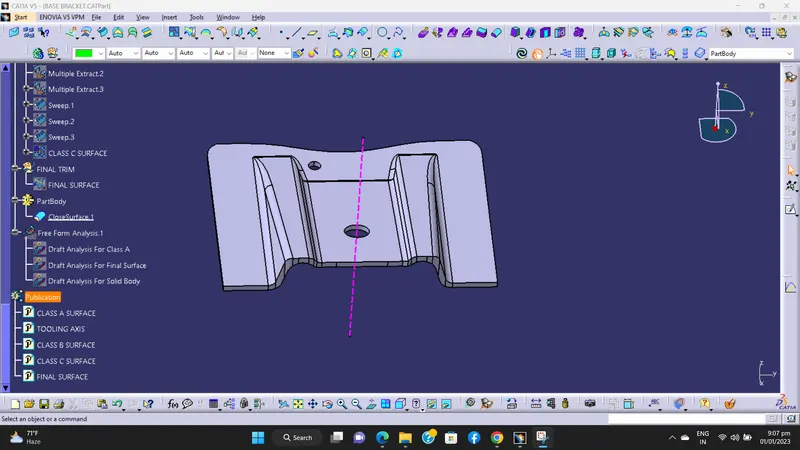
Various Orientations -
1) Isometric view -
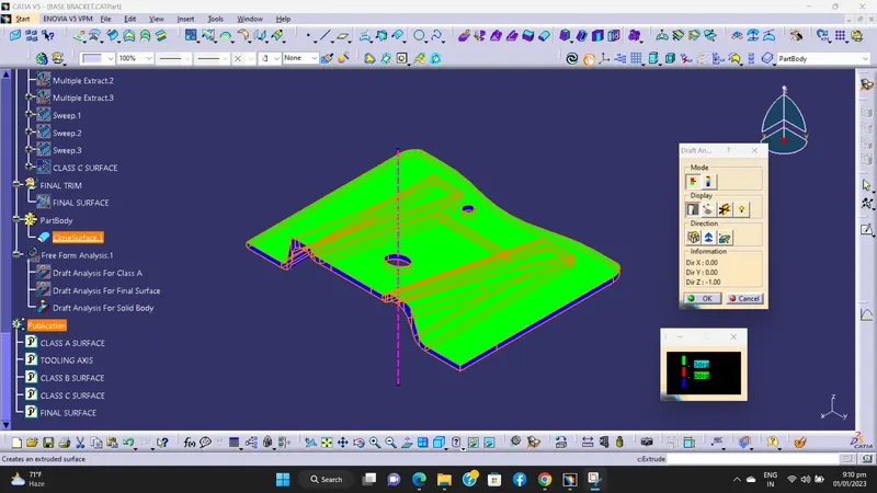
2) Front View -
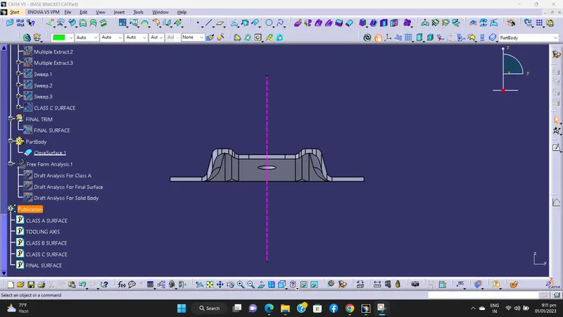
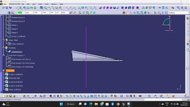
3) Side View -
4) Top View -