Week 8 - Challenge 1 - Base Bracket Design
Title: Base Bracket Design Using CATIA V5
Objective: To create the Base Bracket Plastic component through the given Class-A surface. As well as, creating the tooling axis for the given Class-A Surface which is meeting the requirements of the draft angle and at the end perform the Draft analysis on the model.
Introduction: A brace bracket is a hand tool for drilling holes, with a socket to hold the drill at one end and a cranked handle by which the tool can be turned.
Specifications:
Base Bracket Thickness = 2.5mm
Minimum Draft Angle = 3 Degrees
Definitions:
- Class-A Surface: it is a surface created by the styling team which is then given as an input to the plastic designer to create the plastic component. It is the aesthetic surface and the outer most surface.
- Class-B Surface: it is the surface below a certain thickness from the Class-A surface created by the plastic designer. This surface contains all the engineering aspects of a model.
- Class-C Surface: it is the surface which joins the Class-A and Class-B surfaces together.
- Draft: it is the amount of taper or slope given to cores or other parts of the die cavity to permit easy ejection of the casting from the die casting die.
Design Methodology:
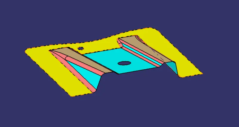
Fig 1: Class A Surface Given
1. Tooling Axis: for creation of the tooling axis, we follow the bisecting lines method.
- First, ensure that the Class-A surface is properly joined and has no discontinuity. Select the boundary command from the toolbars and then select the Class-A surface. A boundary should only appear on the outer edges of the component.
- Then, we decide the proper tooling axis direction with respect to the given component (in this case it is the Z-axis direction).
- After that, we create a point and an axis system on the Class-A surface and then create an intersection by using the intersect command, taking the zy plane of the new axis system and the points as references.
- Then, we create two lines which are on the edges of the two side ribs of the Class-A surface.
- Lastly, we create the tooling axis by creating a bisecting line with the two previous lines on the point that we created on the Class-A surface.
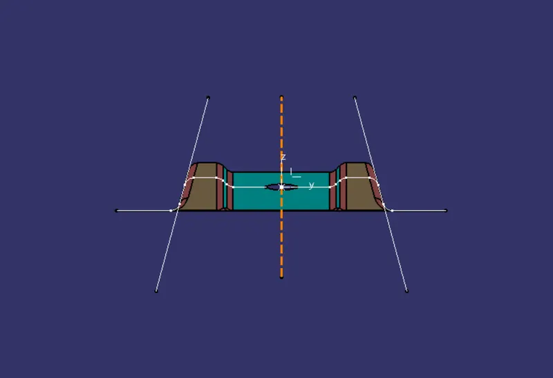
Fig 2: Tooling Axis
2. Draft Analysis: to check whether our tooling axis is proper or not we do the draft analysis.
- Go to insert > analysis > feature draft analysis.
- Align the compass with the tooling axis.
- Then, click on the Class-A surface to see if the it is within the permissible limit of the draft values.
- The Class-A surface should turn green and then draft value should be given as 3 degrees.
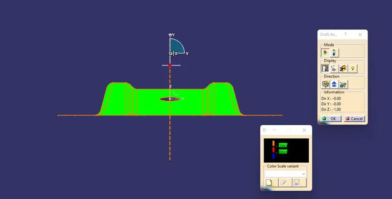
Fig 3: Draft Analysis (Class-A)
3. Class-B: we create the Class-B surface by extruding the Class-A surface by 2.5 mm
- First, we will use the Extract, Un-trim, Extrapolate, Trim and Offset commands on the base surface, the two side ribs and the top plate of the Class-A surface separately to create the desired Class-B surface.
- After that, we will use the Trim command to get our proper desired Class-B surface.
- We will give proper fillets to the edges of the Class-B surface.
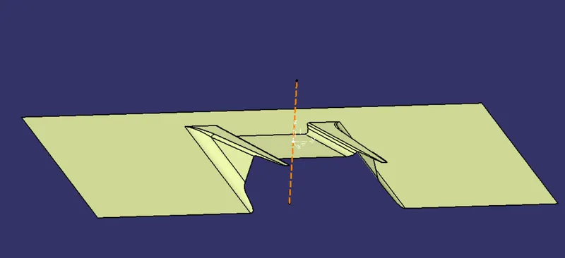
Fig 4: Class-B Surface Final
4. Class-C: we create the Class-C surface by extruding the outer edge boundary of the Class-A surface by 2.5 mm.
- First, we extract the outer edge boundary of the Class-A surface and also the boundaries of the two circles.
- Then, we sweep each of these boundaries using the sweep command. We select the Line option on the sweep command menu, the extracted boundaries as Guide curve 1 and the tooling axis as the draft direction.
- After that, we join all the Class-C surfaces with the Class-A surface by using the Join command.
- Lastly, we use the trim command to join the Class A, B and C surfaces together and obtain the proper desired surface.
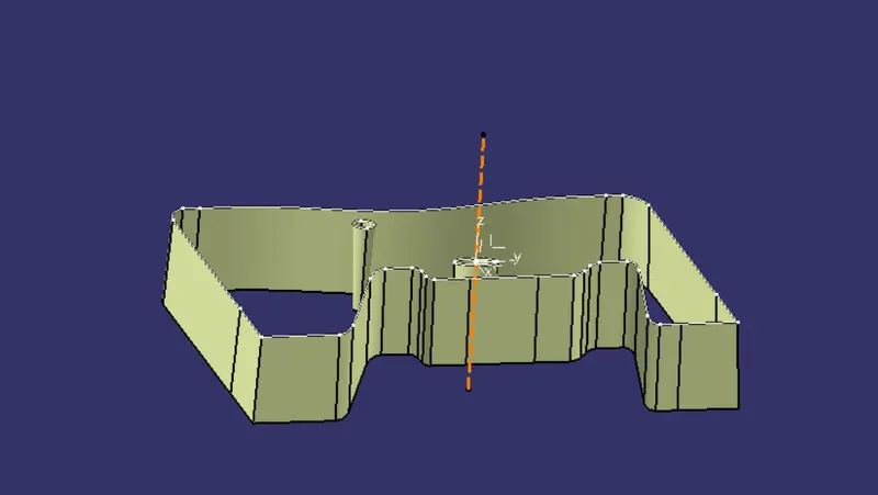
Fig 5: Class C surface Final
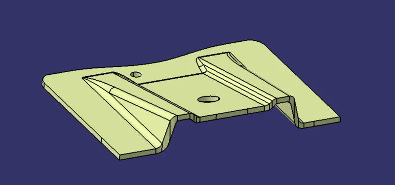
Fig 6: Final Surface
Part Body: we create the final solid body using the Closed Surface command.
- Go to Boundary command and click on the new surface. An error dialog-box should pop-up.
- Go to the Part Design workbench.
- Select the Closed Boundary option and then click on the generated surface.
- A closed solid body is obtained.
Draft Anaysis of the final solid body:
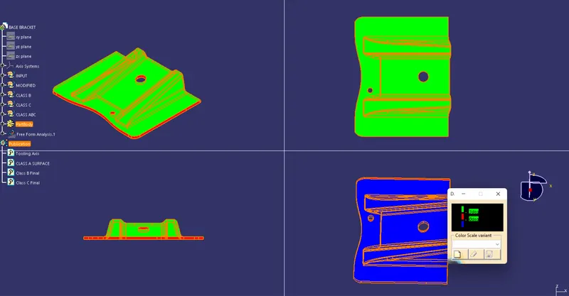
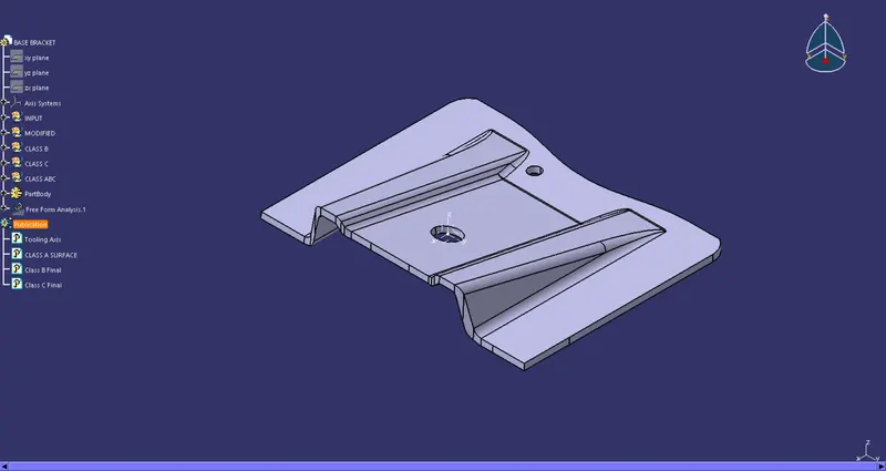
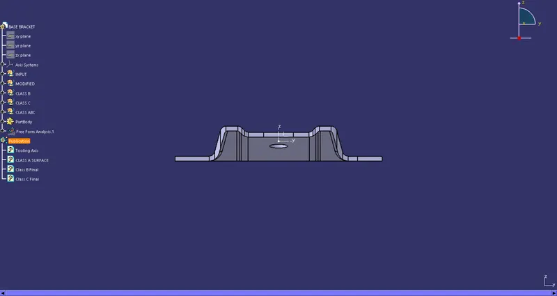
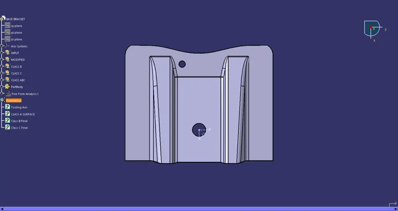
Solid Body Views:
Isometric View:
Front View:
Top View:
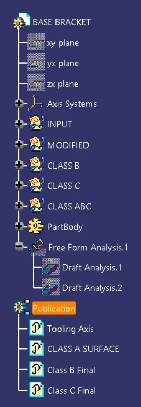
Feature Tree: