Week 8 - Challenge 1 - Base Bracket Design
BASE BRACKET DESIGN BY USING CLASS A SURFACE
AIM:
- To design a Base Bracket Plastic component through the given Class-A surface by creating a tooling axis and draft analysis of the given surface.
DESIGN PROCEDURE:
- To setup the class-A surface and to creating a tooling axis
- add draft angle
- To create a base surface of model
- To create a B-surface
- To create a C-surface and surface model of a base bracket
- To use close surface for creating a solid part model
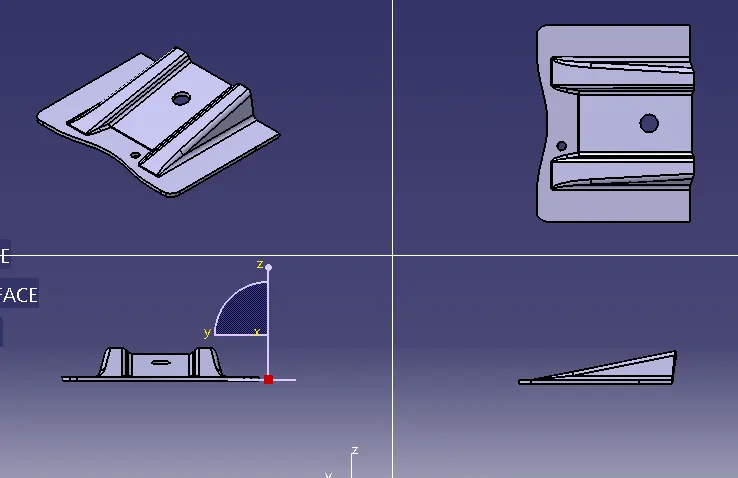
CLASS-A SURFACE:
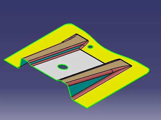
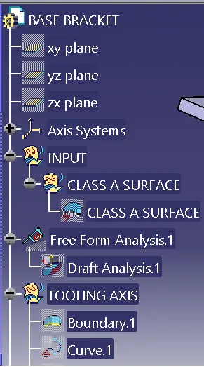
TOOLING AXIS:
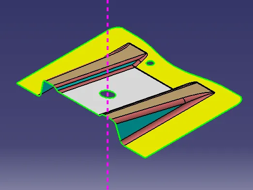
- Tooling axis can be classified into two methods
- direct method
- bisecting method:
- In this model we use bisect method based on the requirement. This method is used for complex components.
- To use boundaries and make bisect the lines for creating a tooling axis
- To ensure the class-A surface is properly joined and has no discontinuity to it.
- To Analyze the surface for to setup tooling axis based on best suitable angle and direction.
DRAFT ANALYSIS:
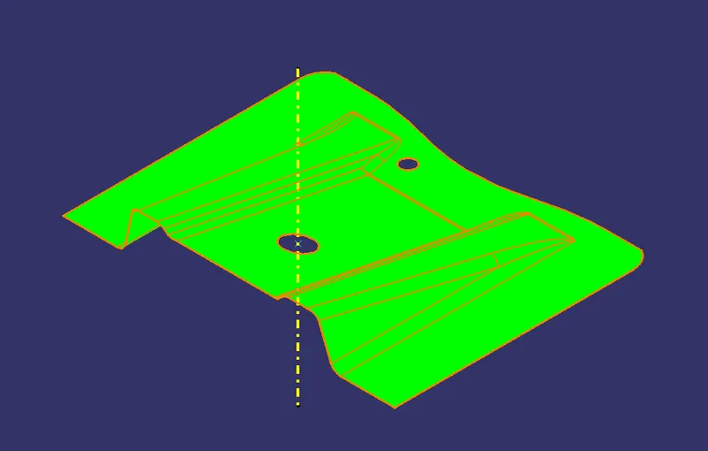
- The Drafting analysis was performed on the class-A surface by using the Feature Draft Analysis command.
- Using this command, the compass was set on the main tooling axis and the Draft angle was changed to 3 degrees.
CREATING CLASS-B SURFACE:
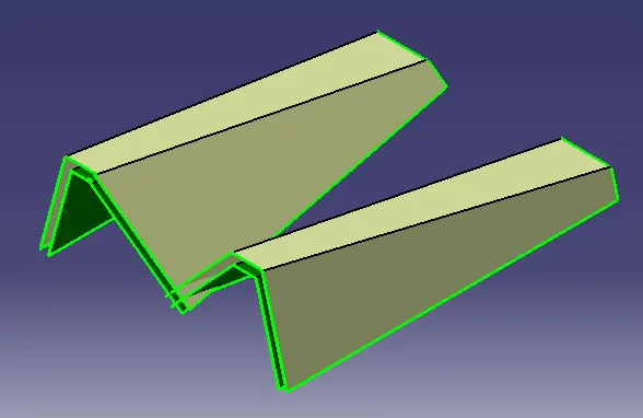
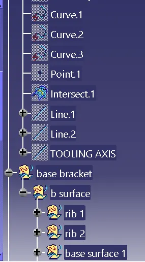
1.RIB:
- To create a rib by extract the rib faces from the class-A surface.
- After extraction to untrim them for collide faces and extend up to some point
- To use Extrapolate for to extend the untrim surfaces
- To use trim tool for remove unwanted surfaces
- To offset the ribs down to 2.5 mm
- BASE SURFACE:
- To create a base surface and extrapolate to meet the ribs for remove unwanted surface
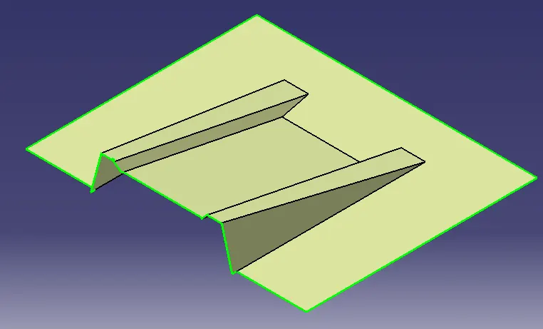
- Base surface with ribs after the trim the unwanted surfaces
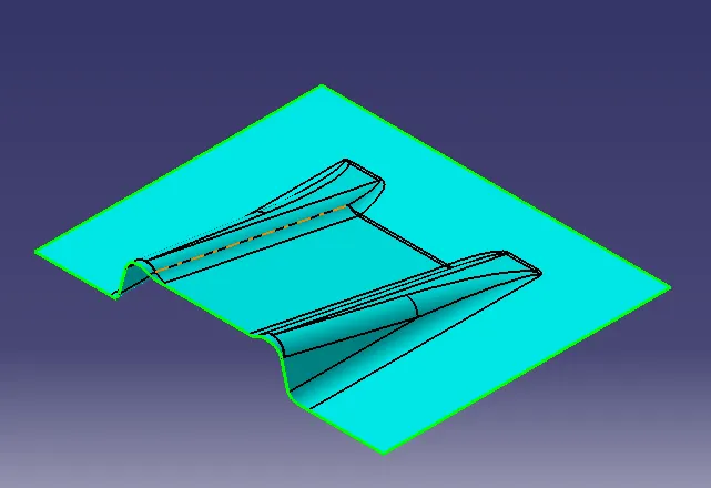
B-SURFACE
CREATING C- SURFACE:
- To create a boundary on the class-A surface and use sweep for extended throughout the B-surface for creating a surface model.
- Similarly holes also created by using swept tool along tooling axis.
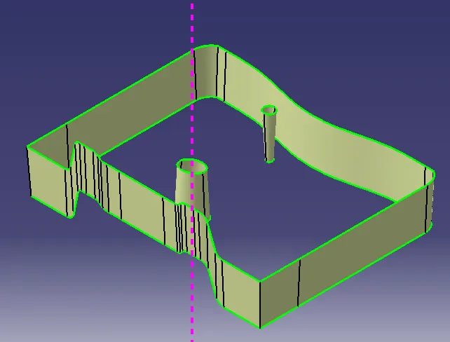
SURFACE MODEL OF A BASE BRACT:
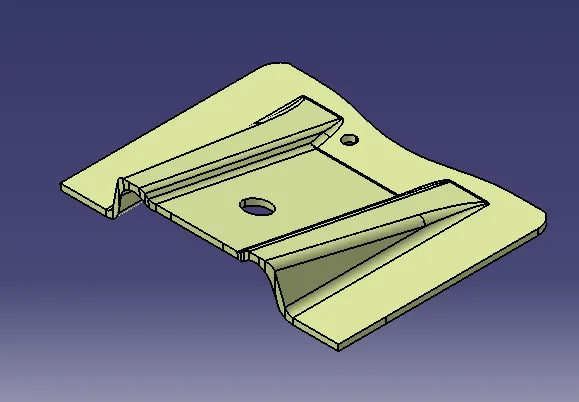
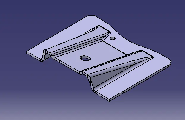
SOLID MODEL OF A BASE BRACT:
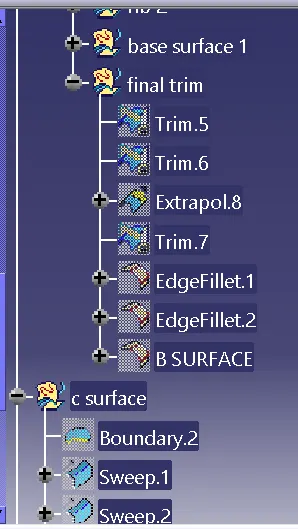
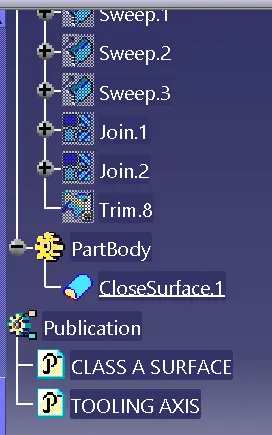
TREE SHOTS:
CONCLUSION:
- To use class-A surface and create Tooling axis, Draft analysis were performed.
- The solid component was created from the surface model.