Photo Realistic Rendering
ASSEMBLY AND RENDERING OF AN AMERICAN CHOPPER
Objective:
The main aim is to designing and assembly of an American chopper by using the tool methodology of sketch (2D modeling), solids (3D modeling) and photo rendering by using solidworks and solidworks visualization.
Introduction:
Solid works is a solid modeling computer-aided design (CAD) and computer-aided engineering (CAE) application published by Dassault Systemes and The SOLIDWORKS CAD software is a mechanical design automation application that lets designers quickly sketch out ideas, experiment with features and dimensions, and produce models and detailed drawings.
Design methodology:
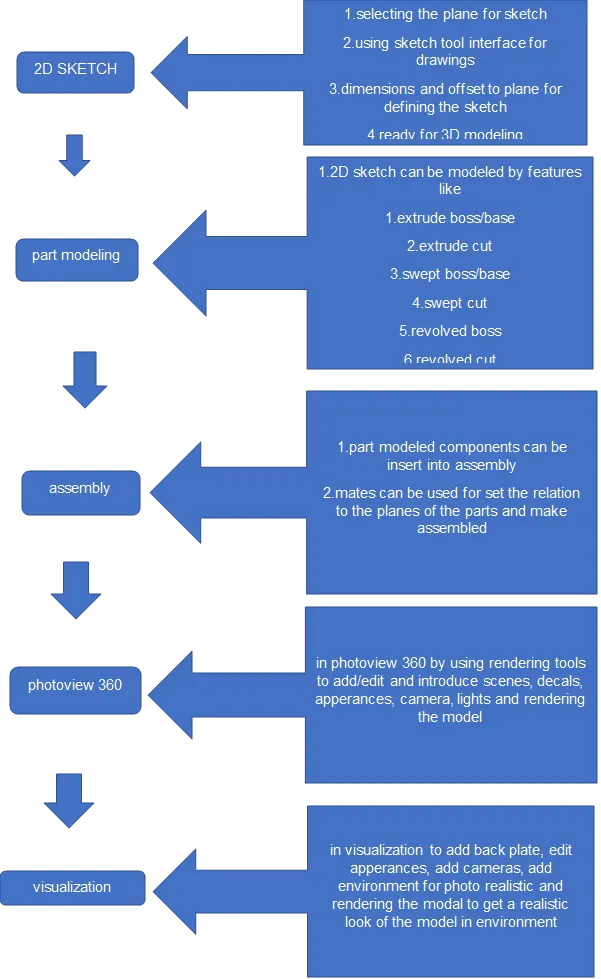
American chopper was modeled by solidworks using part modeling for various part components are required to design separately and assembled to get American chopper.
- due to variety of materials
- various metal approach
like solid, surface.
2D sketch:
To create drawing geometry using 2D sketch by selecting the plane for drawing and given offset distance to the plane and using tools interface for drawings to given dimension for defining the sketch for modeling.
Part modeling:
It Demonstrates the design methods, tools, and features commonly used to make parts.
Parts modeled for chopper:
- Transmission belt
- Kick stand
- Front fender
- Rear fender
- Chain
- Oil tank
- Pedal
- Front wheel
- Rear wheel
- Front fork
- Chassis
- Engine
- Gas tank
Transmission belt:
To design a transmission belt by using 2D sketch tool interface and adding dimensions to fully define the sketch and modeled the part.
Tools used to model the belt are:
- Line
- Offset entities
- Extrude boss/base
- Fillet
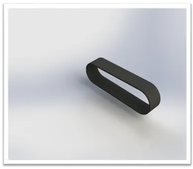
Transmission belt in photo view 360
Kick stand:
To design a kick stand by using 2D sketch and tool interface
- Ellipse
- Spline
- Using reference geometry for creating plane
- Lofted boss/base
- Dome
- Extrude cut
- Fillet
- Extrude boss/base
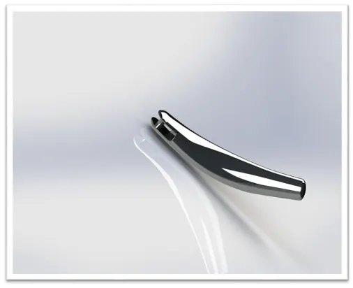
Kick stand in photo view 360
Front fender and Rear fender:
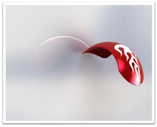
To design a front fender by using
- 3-point arc
- Offset to the plane
- Offset entities
- By using to create construct geometry for revolve
- Revolve boss/base
- Add appearances
- Dynamic mirror entities
- Spline
- Split
- Fillet
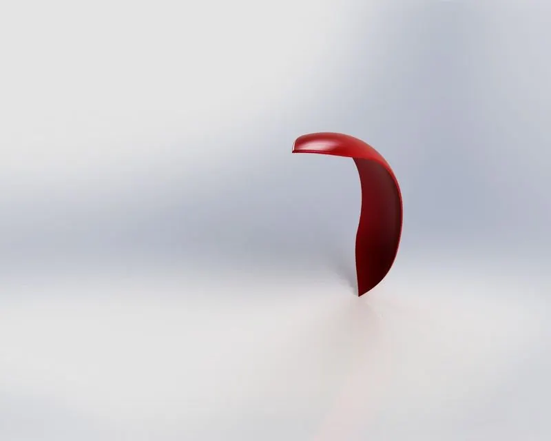
Front fender in photo view
Rear fender:
Chain:
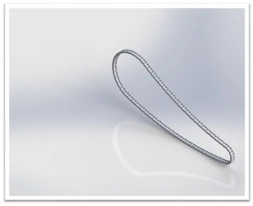
To design a chain by using
- Construction line for reference
- Circle
- 3-point curve
- Trim entities
- Slot
- Make blocks
- Extrude boss/base
- Fillet
- Curve driven pattern
- Mirror
Oil tank:
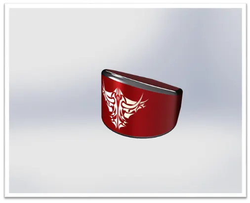
To design an oil tank by using
- Line
- 3-point arc
- Extrude boss/base
- Combine
- Fillet
- Shell
- Add decals in photo view
Pedal:
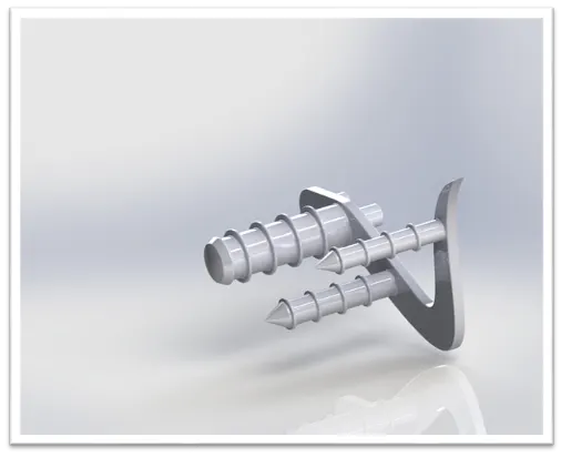
To design a pedal by using
- Line
- 3-point arc
- Extrude boss/base
- Fillet
- Revolve
- Dome
- Chamfer
- Linear pattern
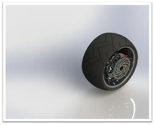
Front and rear wheel:
To design front and rear wheels by using
- Line
- circle
- 3-point arc
- Sketch fillet
- Revolve
- Spline
- Extrude cut
- Revolved cut
- Circular pattern
- Combine
- Fillet
- Chamfer
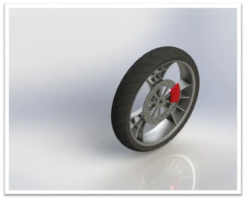
Rear wheel:
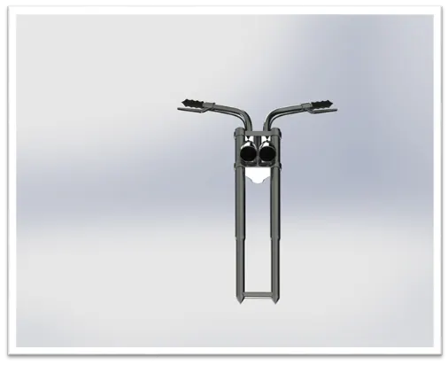
Front fork:
To design a front fork by using
- Line
- Circle
- Revolve
- Extrude boss/base
- Fillet
- Linear pattern
- Extrude cut
- Dome
- Revolved cut
- Curve
- projected curve
- Sweep
- Creating reference plane
- Mirror
- Combine
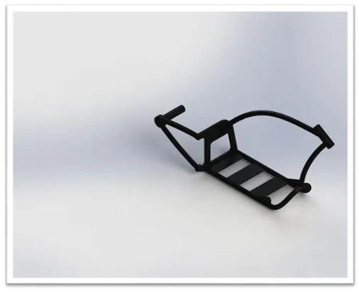
Chassis:
To design a chassis by using
- Selecting the sketch picture
- Curve
- projected curve
- Sweep
- Mirror
- Extrude boss/base
- Extrude cut
- Chamfer
- Fillet
- Reference plane
- Dome
- Split
- Combine
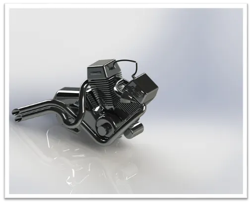
Engine:
To design engine by using
- Sketch picture
- Line
- Circle
- Extrude boss/base
- Fillet
- Revolve boss/base
- Creating Reference plane
- Circular pattern
- Dome
- Extrude cut
- Chamfer
- Linear pattern
- Split
- Sweep
- Curve
- projected curve
- Creating compound curve
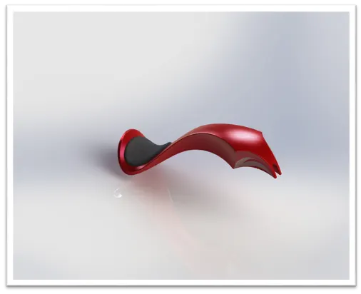
Gas tank:
To design a gas tank by using
- Sketch picture
- spline
- Creating reference plane
- Swept surface from surface modeling
- Surface trim
- Curve
- Lofted surface
- Boundary surface
- Mirror
- Surface knit
- Split line
- Extrude surface
- Fillet
- Boundary surface
- Swept cut
- Shell
Assembly modeling:
In assembly part models can be made together by using mate relation to the components and to get a chopper and it Shows how to add parts to an assembly, specify mates, and use in-context design methods.
Mates:
Mates used to specify the relationship of two parts of the planes for creating an assembly
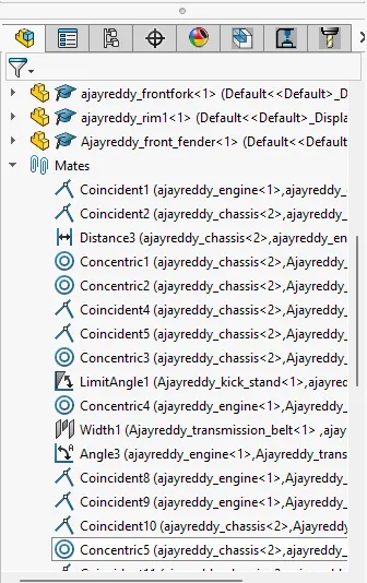
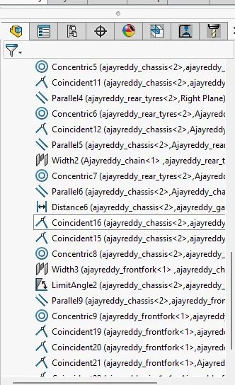
Photo view of assemble chopper:
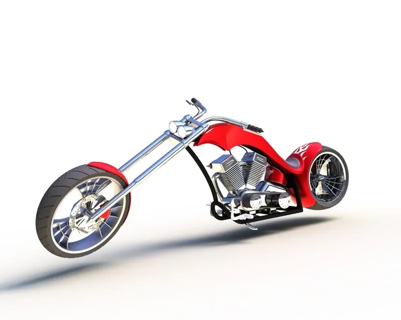
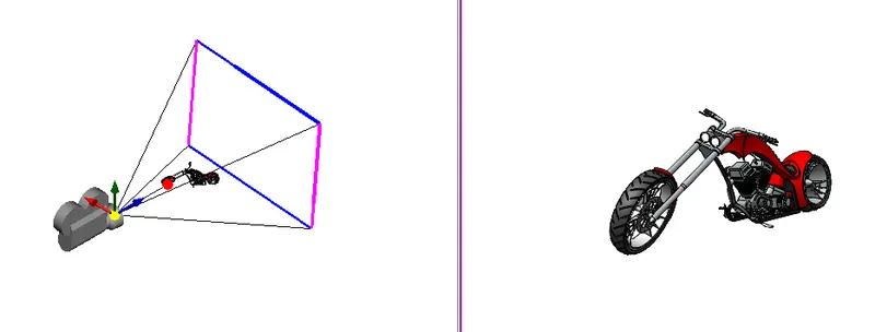
In photo view 360 assemble chopper can used for adding scenes, decals, lights, appearances, and camera for rendering the chopper for realistic photo view.
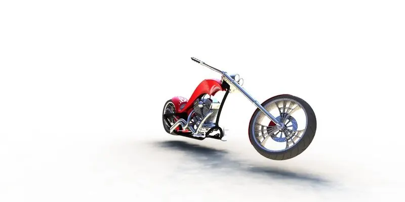
Isometric view
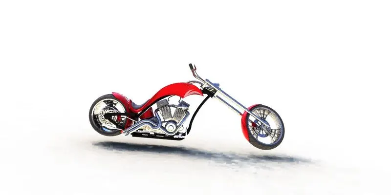
Side view
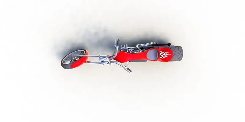
Top view
Camera view
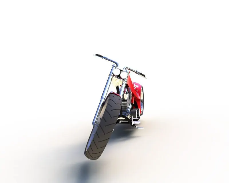
Front view
Solidworks visualization:
The assembly chopper can be photo realistic render visualization by adding scenes, backgrounds, adding 360-degree environments, add cameras, and edit appearances for rendering the model.
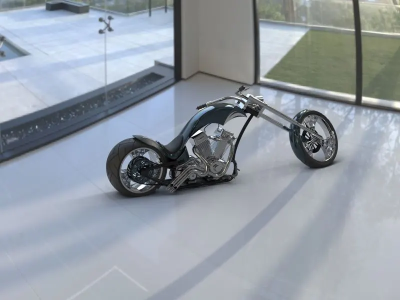
Side view in visualization
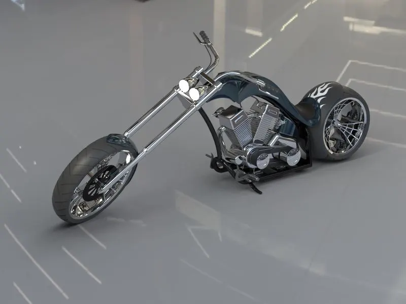
Isometric view
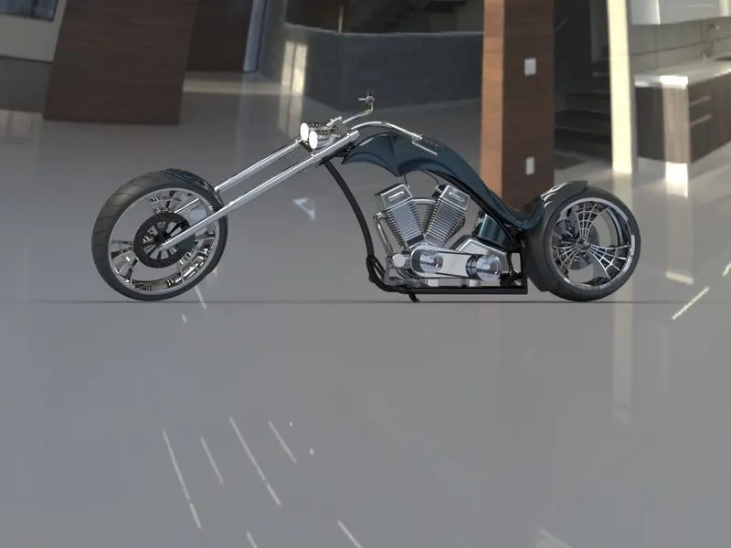
Side view2
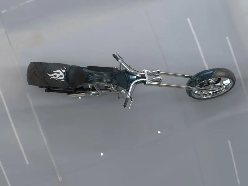
Top view
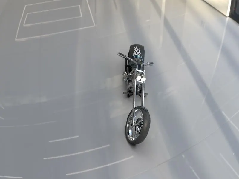
Front view
Conclusion:
To design and rendering of a chopper by using solidworks and visualization, in this project to learn a tool methodology, features like solid modeling and surface modeling, and photo rendering of the model by using photo view and solidworks visualization.