Advanced Sheet Metal Design Using NX Cad Challenge_2_Box Assembly
TO DESIGN A BOX ASSEMBLY BY USING SIEMENS NX CAD
Objective:
The main aim is to design a box assembly by using NX CAD.
Introduction:
Box usually design to storage purpose, like container used for the storage or transportation of its contents. Most boxes have flat, parallel, rectangular sides. Boxes can be varied based on the the required shapes and sizes.
Boxes may be closed and shut with flaps, doors, or a separate lid. They can be secured shut with adhesives, tapes, or more decorative or elaborately functional mechanisms, such as a catch, clasp or lock.
Boxes can used as storage and at a time it protects the inside content from damaging, accidents etc.,
To design a box assembly by creating a
- Box
- Lid
- Hinges
Design methodology:
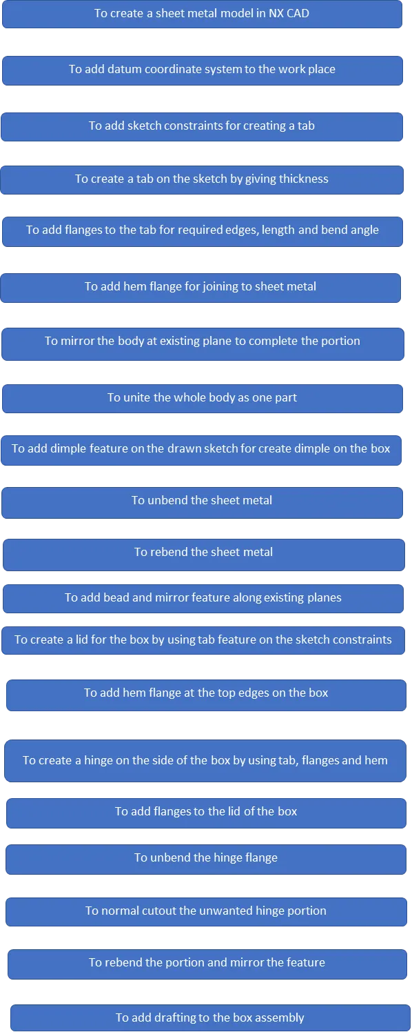
Features used for design a casing:
- Sketch
- Tab
- Flange
- Closed corner
- Hem flange
- Mirror body
- Unite
- Sketch for dimple
- Dimple
- Mirror feature
- Unbend sheet metal
- Rebend sheet metal
- Sketch for bead
- Bead
- Mirror feature
- Hem flange on the box sides
- Tab can be used for box lid
- Add flanges to lid
- For hinge to add tab, flanges, hem flanges and more features.
Sketch:
To setup the coordinate system and draw a sketch by giving dimensions and constraints to the plane, in this model to use origin point and make the rectangular sketch portion for given dimensions.
Tab:
The sketch portion can be extruded by given appropriate and suitable thickness for sheet metal.
Flange:
To add flange to bend edges of the model for required length, direction and bend angle.
Closed corners:
To add closed corners to fill up the opened portion of the edges of the model.
Hem flange:
To use hem flange to joined the two sheet metals without any operation, it is easy method to add sheet metals without distortion and shape of the metal.
Mirror body:
To use mirror body feature to mirror the body at another side by referring the existing plane.
Unite:
To use unite feature for creating the whole part model as a one.
Sketch for dimple:
To add constraint sketch on the required plane for creating dimple by giving the dimensions and constraints.
Dimple:
To add dimple feature to the sketch and given thickness and direction to create a dimple.
Mirror feature:
To add mirror feature to the dimple and it’s sketch constraints by referring the existing plane for creating dimple on the other side.
Unbend:
To unbend the model for further operations by selecting the center face for unbend the sheet metal.
Rebend:
To rebend the model by selecting the feature and make select and drag the left mouse button on the model.
Sketch for Bead:
To create a sketch on the req plane for create a circle for bead.
Beads:
To create a bead on the sheet metal for providing addition strength to the model.
Mirror:
To add mirror feature to bead and its sketch by referring the plane to mirror along the opposite side.
Hem flange on the box:
To use hem flange to the opening four end edges to bend outside for smooth transition.
To create a lid:
To add tab for sketch constraints and given thickness for tab, add flanges to the lid.
Hinge:
To create a hinge for holding the box and lid for opening and closing.
to create a hinge by
- given sketch constraints for creating tab
- Add flange at the edge of a tab by giving angle, direction and length
- Add another flange at edge of the first flange at given angle
- Add open loop hem flange at a given angle for creating hinge
- To unbend the flange for normal cutout operation
- To normal cutout the unwanted material from hinge portion
- To rebend the hinge
- To mirror the hinge feature by referring the plane
Drafting:
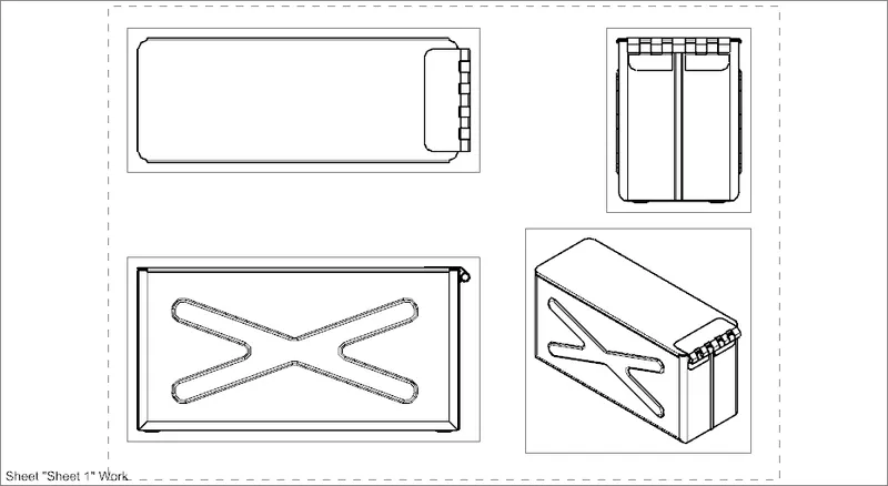
To adding into drawings file for manufacturing the model by referring dimensions.
Box design:
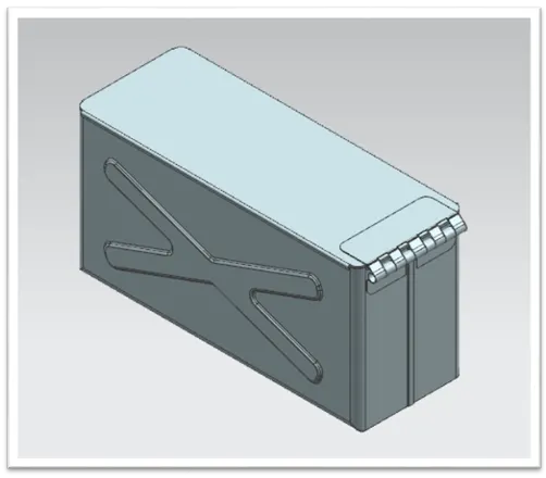
Casing isometric view
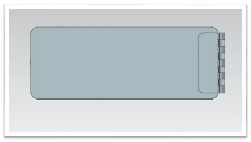
Top view
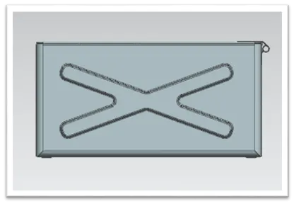
Front view
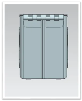
Side view
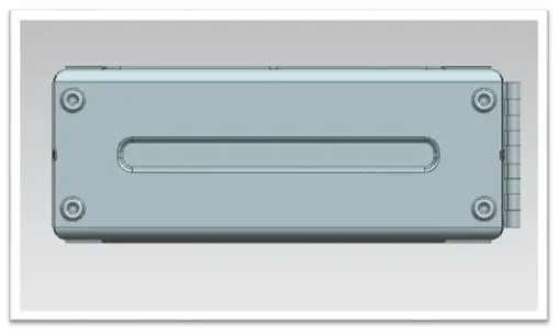
Bottom view
Drafting images:
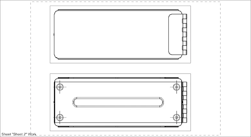
Top and bottom images
Conclusion:
To learn the sheet metal designing and tool methodology by design a box assembly in sheet metal by using tools and it’s features by using NX CAD.