Week 8 - Challenge 1 - Base Bracket Design
AIM:
Create the Base Bracket Plastic component through the given Class-A surface. To begin with, the tooling axis for the given Class-A Surface should be created meeting the requirements of the draft angle and at the end perform the Draft analysis on the model.
Challenge expectations:
- Ensure Proper Tree Structure
- Geometrical sets should have a proper name based on the sketches present inside of it
- All the sketches should be created under the Geometrical set
- Use the Close Surface feature to make a solid body from the surface.
- Publications: Use the publication option and publish the below
- Tooling Axis
- Class A, B, and C surface.
DRAFT ANALYSIS:
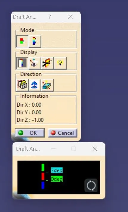
The Draft analysis is performed based on colour ranges identifying zones on the analyzed element where the deviation from the draft direction at any point, corresponds to specified values. Here I am taking the draft angle 0 to 2.6 degree.
PROCEDURE:
- Creating tooling axis
- Open the given CAT part file.
- check for gaps between surfaces for that click on join and then preview
- extract the boundary and dissemble the boundary
- find the correct tooling axis where the Material doesn’t interfere with the tooling axis and all the elements can be created
- create an axis system using at the center of the fan cover
- Intersect the yz plane with respect to the class surface.
- Hide the class A surface and create point-to-point lines on the suspected drafts
- Create a bisecting line with the two lines and point to create a tooling axis
- The tooling axis is created for the component
- Draft analysis
- Before going to drat analysis go to customized view parameter >under mesh >check material and then click ok
- Now for draft analyses go to insert >analysis>feature draft analysis.
- Use the compass to define the draft direction
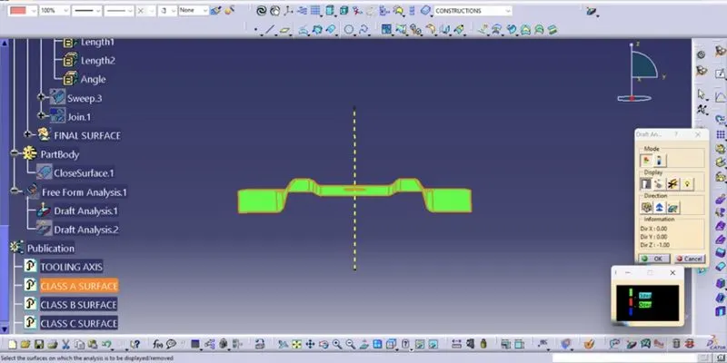
- In the color, scale change the draft angle to 3degree.
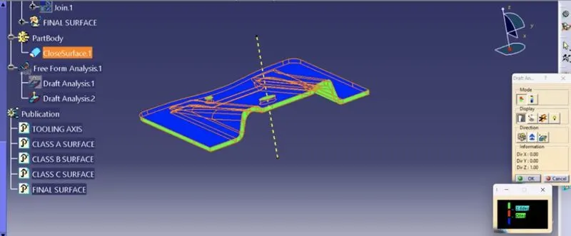
- The component changes to green in an indication of the passing draft angle.
- Use a running point to check the angle of the component.
- The draft analysis is complete.
- Creation of class B surface
- Extract the surfaces from class using multiple extracts and untrim them
- Use extrapolate to make sure that all the untrims are properly intersected to trim and offset the surfaces to 2.5 mm to create the thickness.
- Trim the extra surfaces using the trim command
- Insert them into the new geometrical set and name it with respective part names.
- Apply fillets to the model after creating the entire surface.
- If the fillets are outside the fillet value will be added to the thickness of the component, for instance the thickness of the component Is 2.5mm the fillet value is 3mm so the outside portion value should be 5.5mm to get uniform thickness.
- Perform trims one at a time so that it will be clear to understand.
- Creation of a class c surface
- extract the boundary from the class A surface using the boundary
- Using a disassembly tool to divide the boundary as the boundary contains domains.
- Use sweep command >choose profile type line>subtype as with draft direction>choose guide curve and draft direction >give draft angle as 3 degrees>preview.
- After getting sweep then trim the output with class B surface to get the final output.
- Now open the part design workbench and use a close body surface to create a solid component.
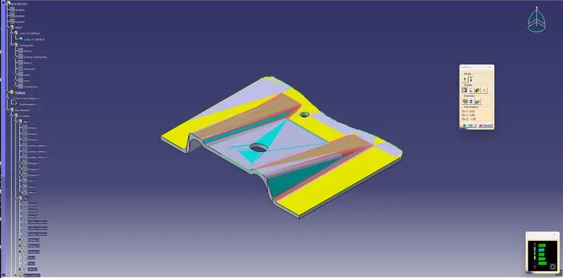
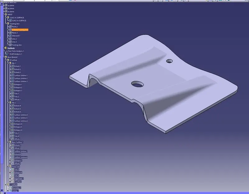
(A) DRAFT ANALYSIS (B) ISOMETRIC VIEW
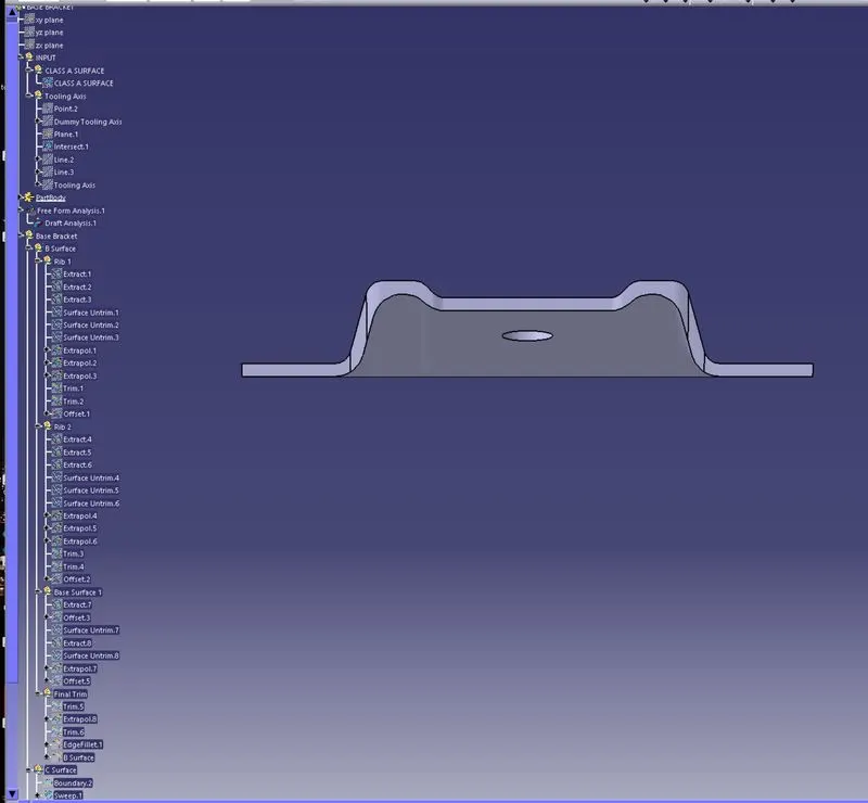
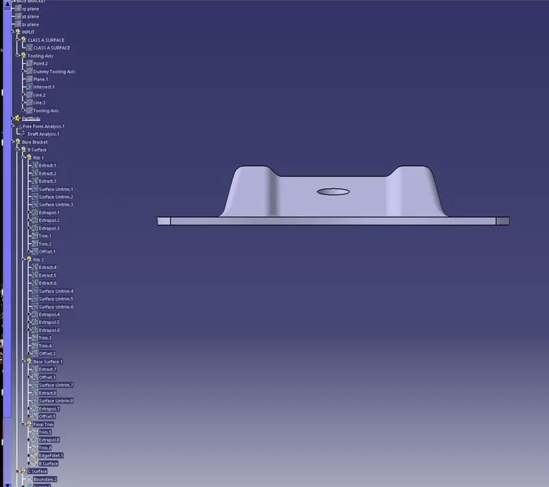
(C) FRONT VIEW (D) BACK VIEW
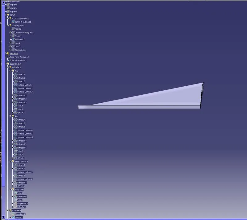
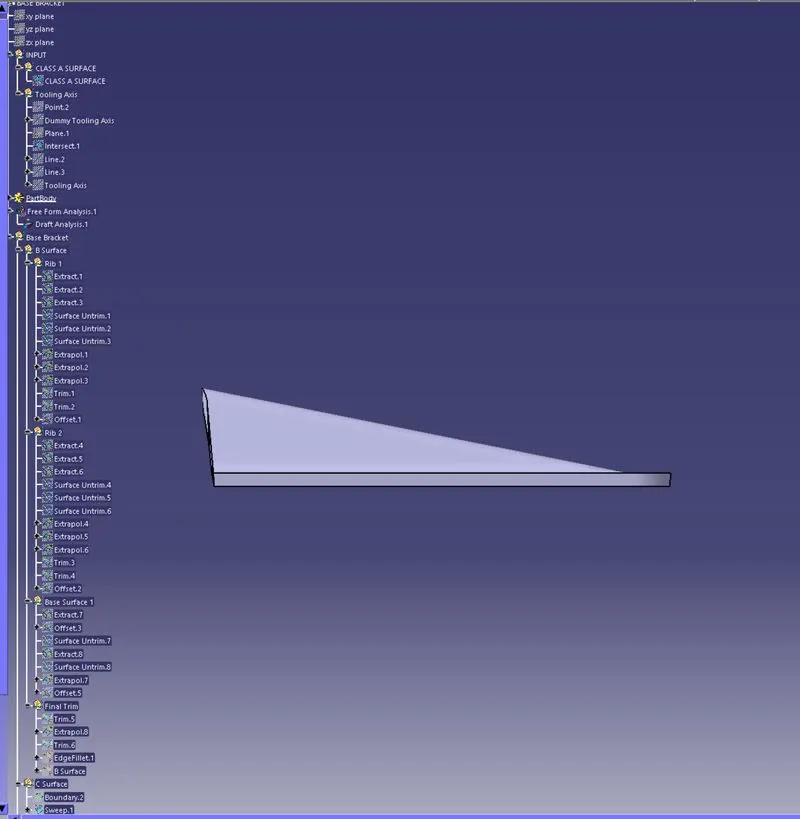
(E) LEFT-HAND SIDE VIEW (F) RIGHT-HAND SIDE VIEW
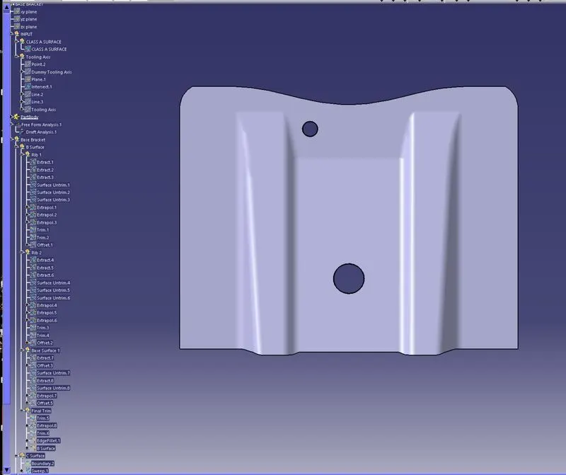
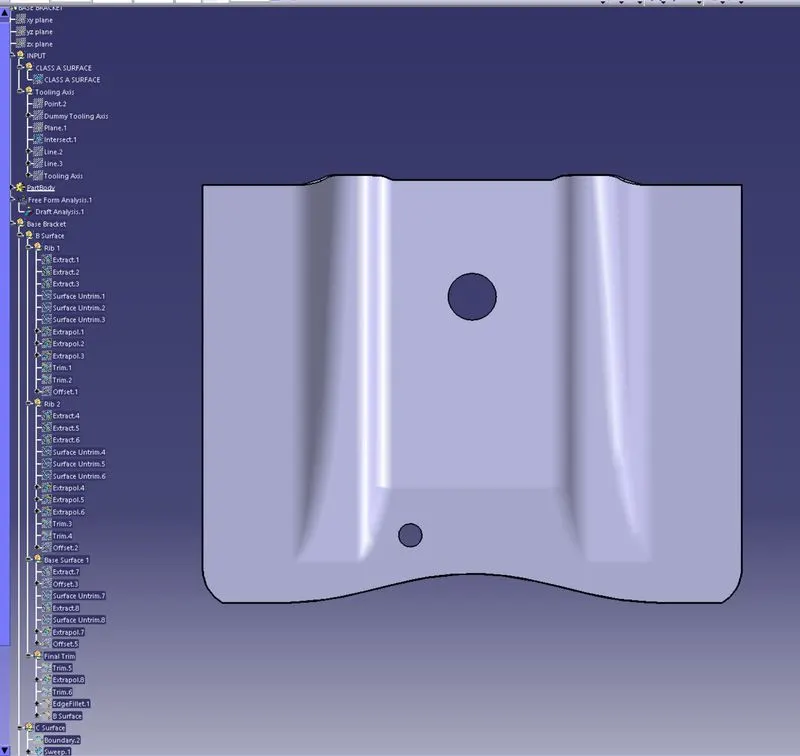
(G) TOP VIEW (H) BOTTOM VIEW