Week 8 - Challenge 1 - Base Bracket Design
Drafting
In manufacturing process to release the core and cavity without damages drafting angle is provided in them.
Tooling axis
The axis along with which the core and cavity is removed is known as tooling axis.
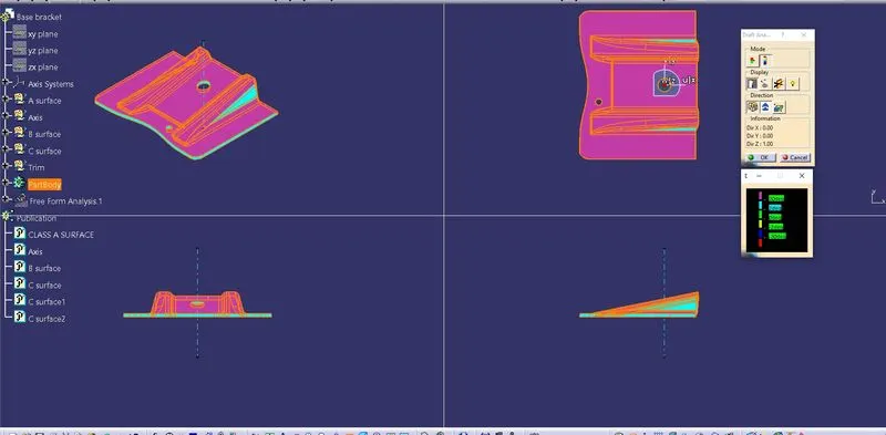
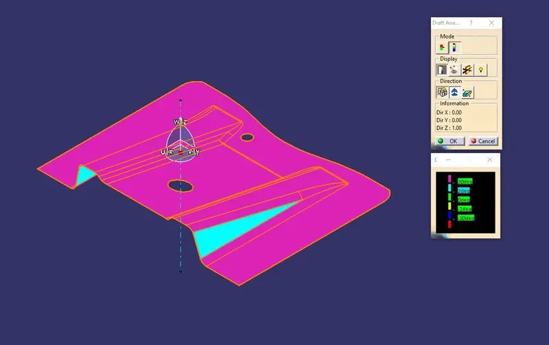
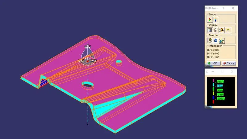
Drafting analysis
Draft angles in a component can be positive or negative along the tooling axis. For a smooth release of the mould and component in automotive industry standards follow 3degree draft minimum along the tooling axis.
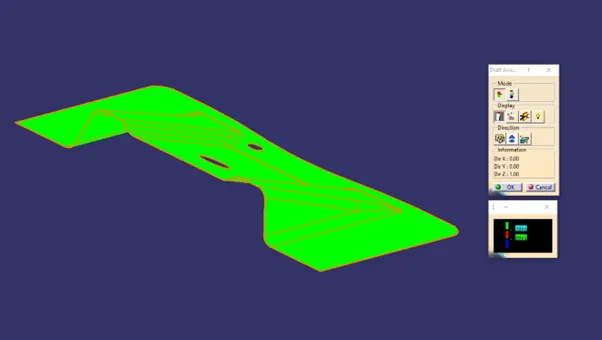
To perform drafting analysis in CATIA following steps are followed,
- Go to Insert > Analysis > Feature Draft Analysis.
- Choose a mode of analysis quick or full.
- Under display mode select color scale.
- Under direction compass can be used to determine the draft direction, we can also fix or inverse the draft direction.
- Pick on the surface to perform the draft analysis using CATIA.
- With the help of color scale, we can understand the available draft angles along a tooling axis.
Tooling axis creation
- Line
Firstly, we have to determine the direction for creating a tooling axis for our component. With a point on component surface generate a line along the determined direction. Thus, the line becomes our tooling axis for our component.

- Bisecting line
This is another method to create a tooling axis.
- Create a point on the component surface.
- Generate a plane through the point.
- Using the component surface and generate plane at the point create an intersection to give us the 2D profile of our component along the drafting axis.
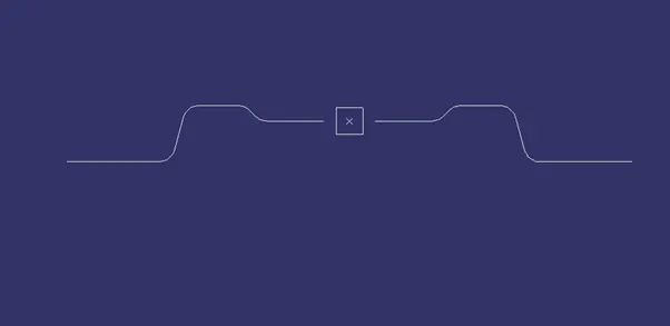
- From the intersection curvature create two lines.
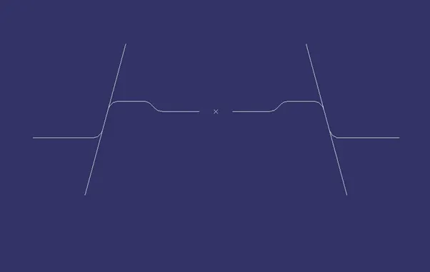
By bisecting these two lines through the before created point another line is formed. This line becomes our tooling axis for our component.
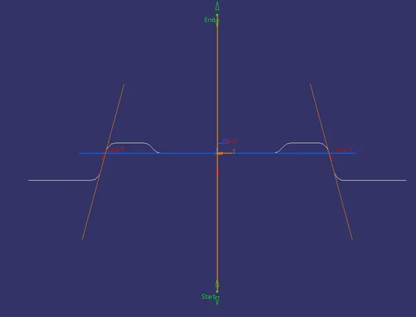
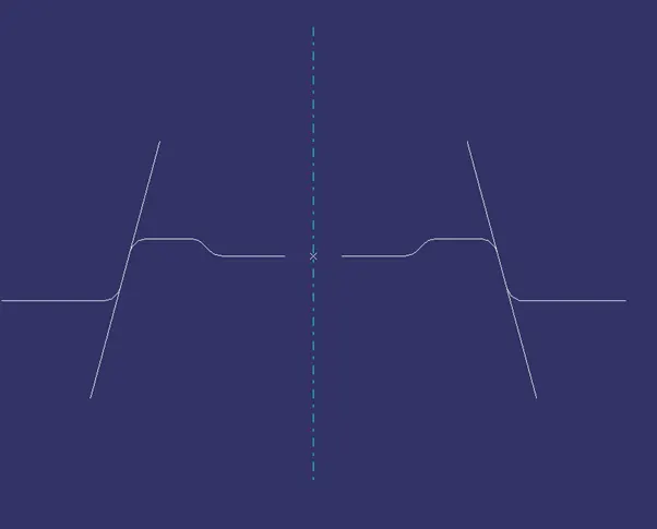
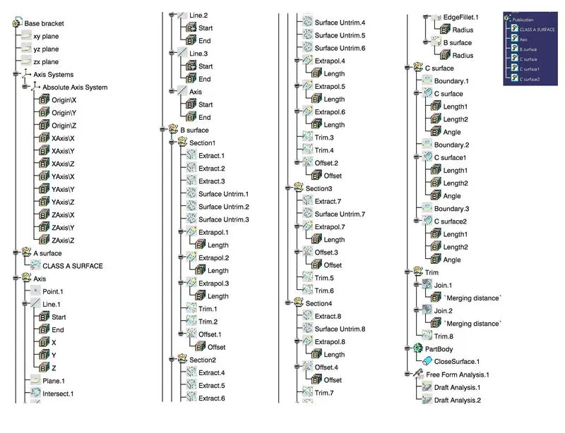
Kindly find the below attachment.
-KSR