Photo Realistic Rendering
CHOPPER BIKE
Main objective:
To design a 3D model of a full-scale chopper bike using Solid Works software by using part build and assembly features. Part build helps us in designing different parts of the yacht. While the assembly feature helps us understand the overall interactions of all the working parts relative to one another.
Introduction:
A motor bike typically operates on the basic principle by using Internal combustion engine to generate power and is transmitted through chains to wheel which drives the bike forward i.e., energy is converted to work done by laws of thermodynamics. Modern day bikes come with various design and purpose. In our case chopper bike is popular for its ergonomic design to cruise for long drives.
Flow chart:
|
1 |
Transmission belt |
|
2 |
Kick stand |
|
3 |
Front fender |
|
4 |
Rear fender |
|
5 |
Chain |
|
6 |
Oil tank |
|
7 |
Pedals |
|
8 |
Front wheel |
|
9 |
Rear wheel |
|
10 |
Front fork |
|
11 |
Chassis |
|
12 |
Engine |
|
13 |
Fuel tank |
|
14 |
Assembly |
|
15 |
Render |
Transmission belt:
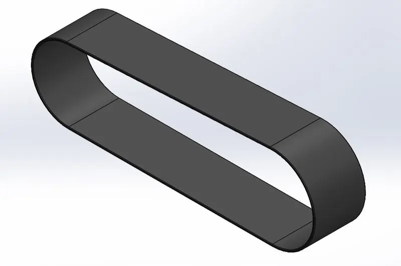
Transmission belt is used to transmit the power onto two relative rotary mechanical shaft. It is made up of elastic material mostly rubber belts for efficient power transmission. In this case we are going to use simple sketch, features like boss extrude and fillet option to create our transmission belt. Added appearance accordingly.
Kick stand:
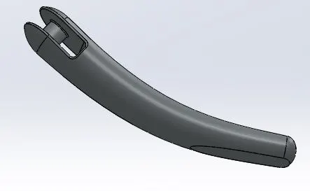
It is used to support the bike while it’s parked in stationary position. Kick stands are very handy easy to use than center stand as pulling the weight of the bike is harder. It is coupled with a tension spring to retract and deploy as when required.
To design our kick stand we use plane feature and sketches, then we use loft feature to create our stand. Features like cut extrude and fillets are applied as necessary. Dome feature is applied to give an appealing look. We use split feature to create a flat portion on our kick stand so that it has a nice contact with the surface when it is used to park the bike.
Front Fender:
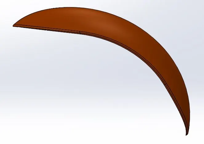
Fenders are used in vehicles to cover the tires. It plays as a guard against mud, stones and other tiny objects that might fly off when it comes in contact with tire when its moving at high speed.
We model our front fender with sketch and revolve feature to a certain angel. Then use split lines to cut off the edges and use fillet to round of the edges. In this model we give sienna appearance to the fenders.
Rear Fender:
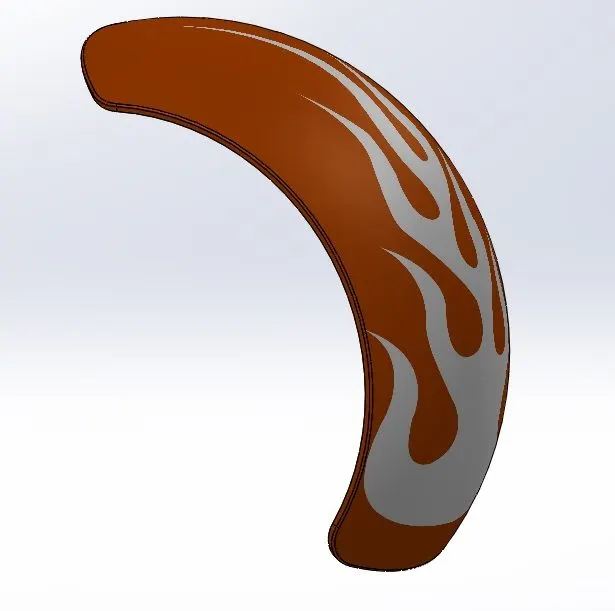
We model our rear fender with sketch and revolve feature to a certain angel. Then use split lines to cut off the edges and use fillet to round of the edges. And use shell feature to provide a casing look. We also add a nice decal to our model.
Chain:
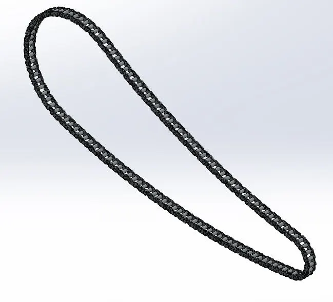
Chain is used to transmit the motion form driver shaft to the driver shaft with the use of gear sprockets.
To model our chain link features like boss extrudes, fillets, circular patterns and mirror option were used to obtain the results. Delete body option was used to remove excess feature to match the curvature of the chain.
Oil tank:
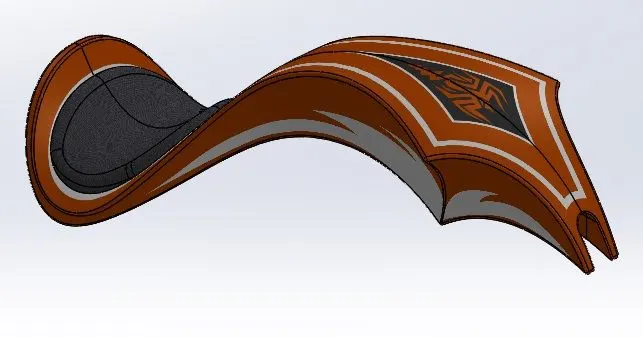
As the name suggest it’s a container to store lubrication oil.
To design our oil tank, we use sketch and boss extrude feature to overlap two bodies and then use combine feature to get the common denominator design. Then use fillet and shell feature to complete our design. Sienna appearance and decal is applied to our model.
Pedals:
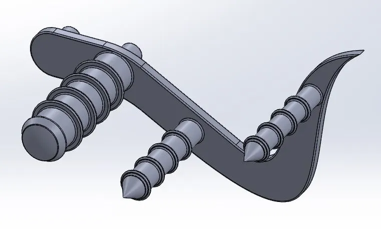
Pedals are use in bikes to rest our feet while riding.
We use features like sketches, boss extrudes, revolve and linear pattern to design our pedal. Fillet, chamfers and dome features are used to give a more finished look.
Front wheel:
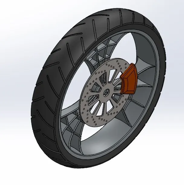
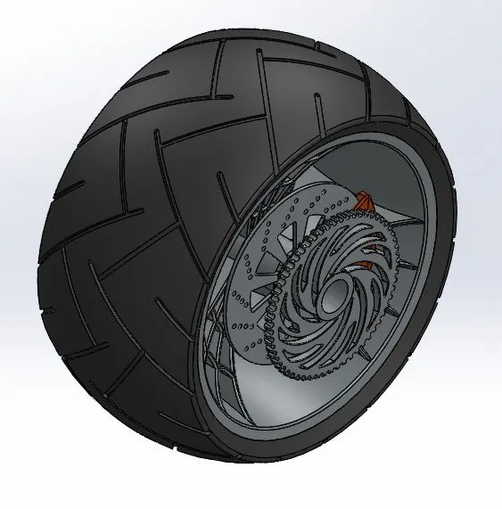
Wheels are used in vehicles to move in the desired direction with the help of power transmission. These are circular shaped objects use rotational motion to facilitate to movement of the vehicle.
In our design we revolve feature to make the rim. Use boss extrude, cut extrude, cut revolve and circular pattern to create our spokes. Then combine the two bodies into one. To create our brake disc we use boss extrude, cut extrude, fillet and circular pattern. To create the brake caliper we use boss extrude, chamfers and fillets. To make our tire we use revolve, cut extrude and circular pattern the tread marks on the tire. We add appearance as needed.
Rear wheel:
Above steps of designing the front wheel is followed for rear wheel as well. And the gear sprocket is designed in the rear wheel using boss extrudes, chamfers, cut extrudes, fillets, circular patterns and revolve features. Appearance is applied as necessary.
Front fork:
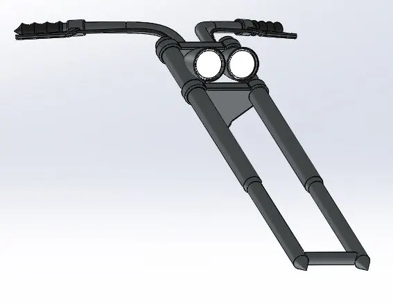
It is a connecting rod between front wheel and its chassis. It is used to steer the bike; maneuverability is dependent on the design of the front fork.
Handle bars, brake lever, head lamp, front telescopic suspension, front wheel axle mount make our front fork.
We use revolve, extrude, fillet, to create our connectors and front shafts. Then use revolve, dome, cut extrude, cut revolve and fillets to create our head light. Use copy and move to create another head light. Use projected curve, sweep, extrude, fillets to create handle bar and brake lever. Use mirror and combine feature to finish our model. Appearance and material are added.
Chassis:
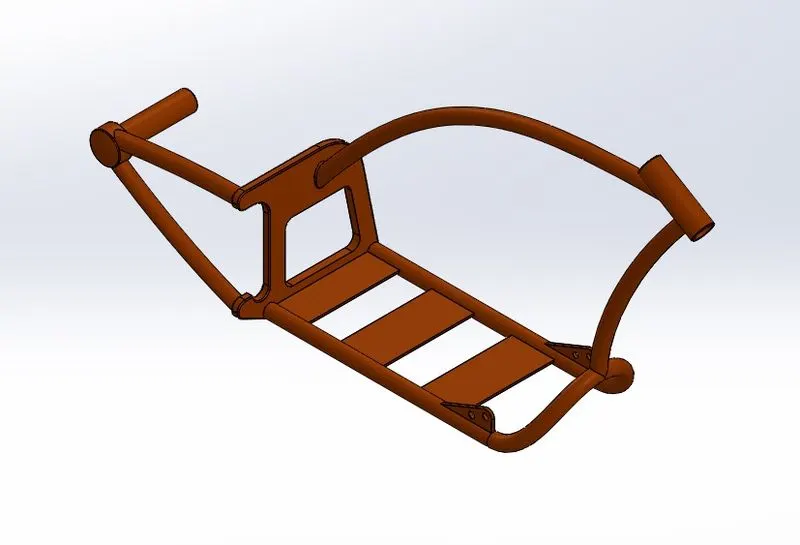
It is the frame structure that is used to mount and connect other parts of the vehicle. Chassis is a load bearing frame work for vehicles.
We use features like boss extrudes, fillets, revolves, domes, cut extrudes, chamfers, splits, mirrors, sweeps, combines and planes are used to design our chassis. We add appearance as well.
Engine:
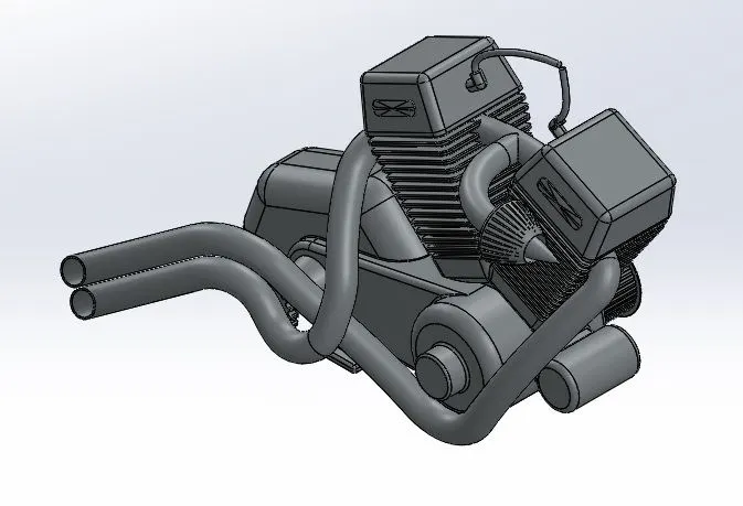
When a thermal energy is converted into mechanical motion with the help of piston cylinders, cam valves and rotary shafts the assembly is known as an engine. We use internal combustion engine to obtain better efficiency for the use of gasoline.
We use features like boss extrudes, fillets, revolves, circular patterns, domes, cut extrudes, chamfers, splits, mirrors, sweeps to design our engine. Projected curve, composite curves and sweeps are used to create exhaust pipes from our engine.
Fuel tank:
Fuel tank is the storage container that is used to store the gasoline.
We are designing the fuel tank and seat for our chopper.
We use features like surface sweep, surface trim, surface knits, projected curves, surface lofts, boundary surfaces, split line, mirror, surface extrude, cut sweep, fillets and shell to complete our design of our fuel tank. Decals and appearances are added as required.
Assembly:
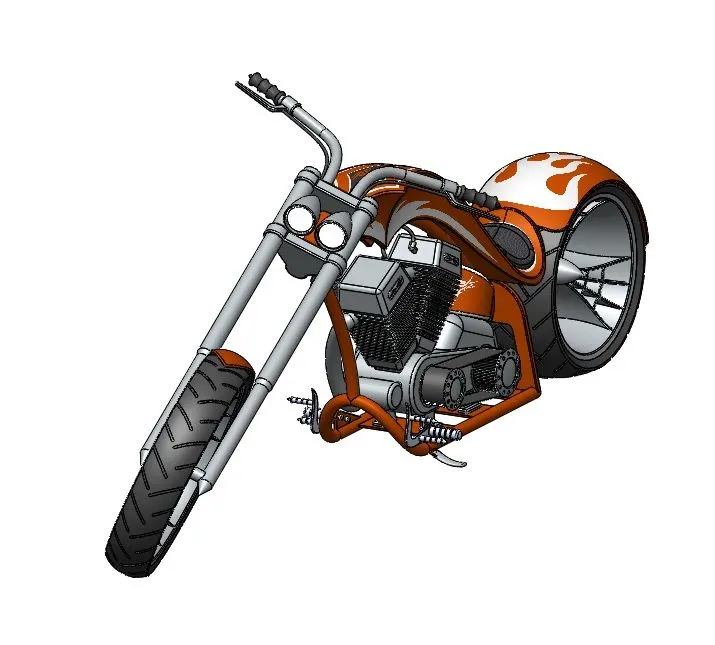
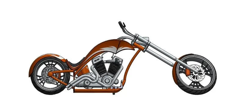
In solidworks assembly certain individual part files are added with reference to the chassis like Engine, pedal, kick stand, front fork, fuel tank, rear wheel. Front wheel is assembled with reference to front fork while front fender is assembled with reference to front wheel. Chain and transmission belt are assembled with reference to engine. And lastly the rear fender is assembled with reference to rear wheel.
Mate features used are coincident, distance, concentric, limit angle, width, angle and parallel. We use mirror option to create a new part of the pedal on the other side and our assembly is done.
Rendering:
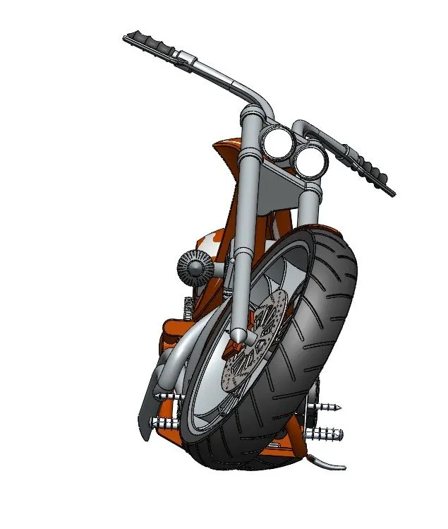
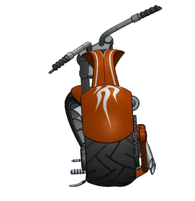
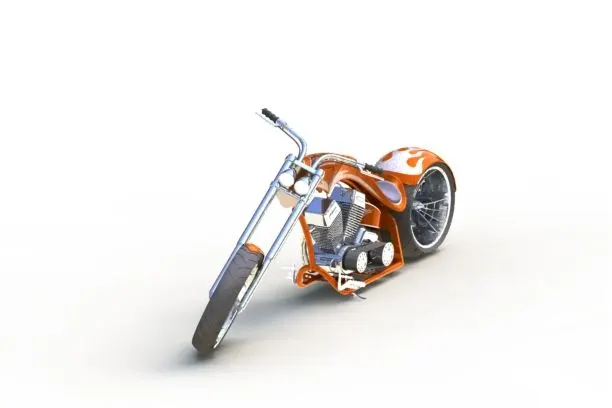
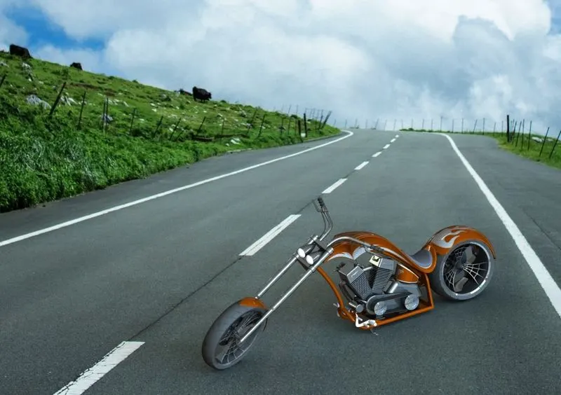
We use photoview 360 for rendering images in solidworks to obtain realistic images of our chopper bike. The above said can be accessed in render tools option in tools. To get the best possible rendered images we proceed with using decals and appearance, setting up camera, background image, adding materials and lights if necessary.
Conclusion:
We learned different types of components in a chopper bike along with how to design them using solidworks. Assembly is done while adding material, appearances and decal. Photoview 360 and solidworks visualize were used to complete our realistic render of our chopper model.