Challenge 2- Comparing the performance of three types of beams under bending load.
Aim
To compare the performance of three types of beams under bending load using solidworks simulation and to suggest the best out of the three obtained results.
Introduction
Finite element analysis is used to solve numerical differential equations of complex parameters used in engineering and mathematical models. Key feature of FEA is using differential equations as it simplifies and provide the following:
- Accurate representation of complex geometry
- Inclusion of dissimilar material properties
- Capture of circumscribed effects
- Uncomplicated total solution
Basic theory
FEA involves dividing the problem into small number of smaller sub domain that represent a set of element equations to the original problem. Thus, unifying set of element equations to form the final calculation. The FEM approximates a solution by minimizing an associated error function via the calculus of variations. Typical problem areas of interest include structural analysis, heat transfer, fluid flow ...etc. Studying or analyzing a phenomenon with FEM is known as finite element analysis (FEA).
Methods of solving engineering problems:
- Analytical method
Usage of derived mathematical formulae.
- Experimental method
Requires performing experiments and recording the solutions as long the setup is well defined.
- Numerical method
Using mathematical tools to obtain approximate solutions for complex areas and volumes.
General steps in analysis:
- Pre-processing
- Geometry check
After importing the CAD model, it is made sure that there are no alterations in our model.
- Meshing
Model is discretized into smaller elements for meshing.
- Quality check
Quality of the meshing is checked during this step.
- Boundary conditions
This includes the fixtures, loads, values of loads, initial conditions of the model, material of the model… etc.
- Processing
Software computes the mathematical calculations based on the boundary conditions provided for FEA.
- Post-processing
Visualization of the data form the simulation to obtain result or verify the hypothesis or redesign to obtain the desired outcome.
Case setup
We have three beams of different cross-sections but of length 400mm each and the applied load is 1500N on smaller faces to develop bending in the corresponding beams. By constraining one end of the beam and with the applied force the stress, strain and displacement results are obtained and compared for three different beams taken as case 1-Rectangle beam, case 2-I beam and case 3-C beam.
Solidworks simulation
- Create a new study under simulation choose static option.
- Apply the type of material to the part to imbued with mechanical, chemical and thermal properties, in our case we use Alloy steel.
|
1 |
Elastic Modulus |
2.10E+11 |
N/m^2 |
|
2 |
Poisson's Ratio |
0.28 |
N/A |
|
3 |
Shear Modulus |
7.90E+10 |
N/m^2 |
|
4 |
Mass Density |
7700 |
kg/m^3 |
|
5 |
Tensile Strength |
723825600 |
N/m^2 |
|
6 |
Compressive Strength |
N/m^2 |
|
|
7 |
Yield Strength |
620422000 |
N/m^2 |
|
8 |
Thermal Expansion Coefficient |
1.30E-05 |
/K |
|
9 |
Thermal Conductivity |
50 |
W/(m·K) |
|
10 |
Specific Heat |
460 |
J/(kg·K) |
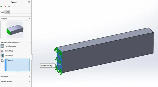
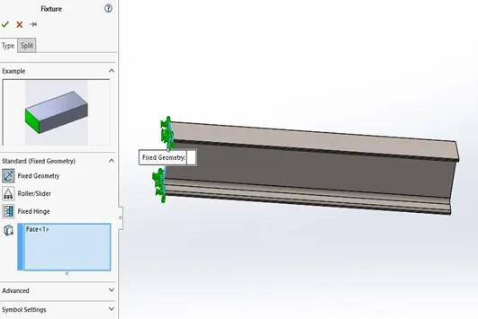
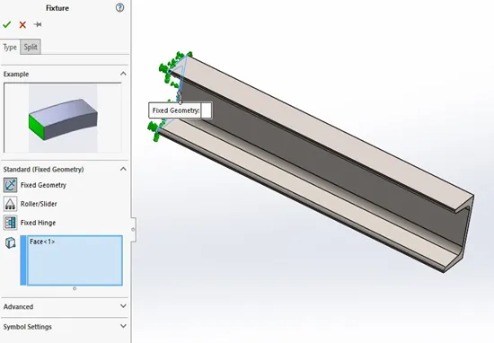
- Fixtures helps in constraining our design. We have to define the edge to be fixed in our design.
Case 1
Case 2
Case 3
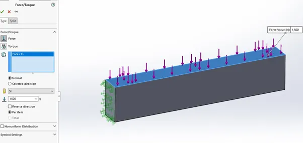
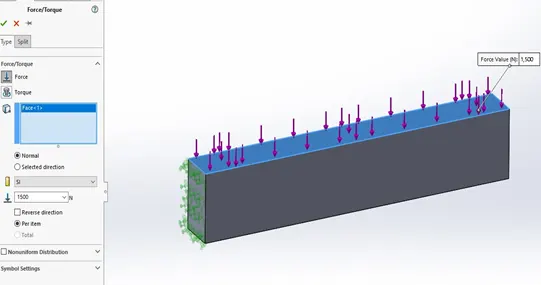
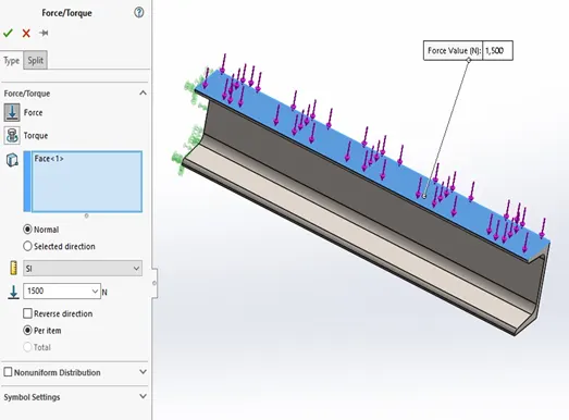
- Under external loads apply a bending force of 1500N in our model.
Case 1
Case 2
Case 3
Plots and animation
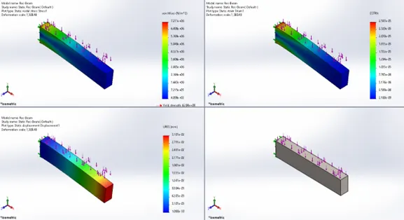
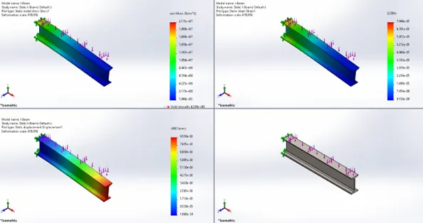
Once our simulation is done, we obtain the stress, strain and displacement bar chart and animation to better understand how material deforms under the applied conditions and compare the results of three different cases.
- Case 1 stress, strain and displacement plot
- Case 2 stress, strain and displacement plot
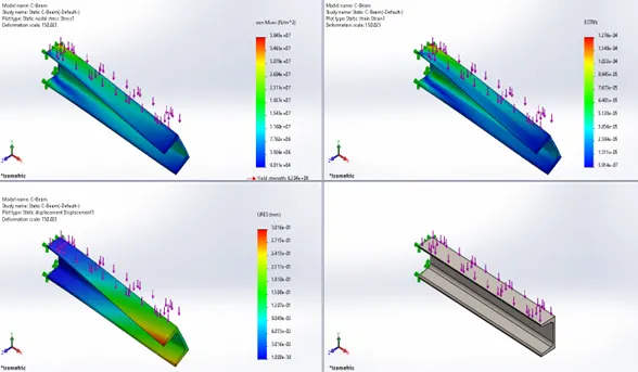
- Case 3 stress, strain and displacement plot
Observation and conclusion
A linear elastic isotropic material is used to compute the relation between the force applied to the object and the corresponding change in shape. In other terms the stress and strain in the material.
With the defined conditions the change in shape of the beams is achieved within the yield strength of the material. Hence the deformation is in the elastic region of the curve thus the deformation is not permanent thus after removing the initial force conditions the material will revert back to its original state.
From the stress, strain and displacement plot we can concur with theory that the case1 is the better out of the three beams. In case 1 the maximum stress incudes is 7.211e +06 N/m^2 which is lower than case 2 (2.111e +07 N/m^2) and case 3 (3.845e +07 N/m^2). The same goes for the strain and displacement values case1 has better values out of the three. Thus case1-Rectangle beam provides the best performance for the load of 1500N out of the rest.
With the help of solidworks simulation above plot observations are obtained by comparison case1 (rectangle beam) is the better out of the three beams of our case study.
Kindly find the below attachments.
-KSR