Week 8 - Challenge 1 - Base Bracket Design
DESIGN AND DRAFT ANALYSIS OF BASE BRACKET
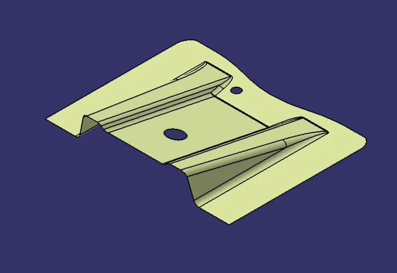
Class A surface
Draft analysis
Draft analysis is done to check plastic parts moldability for the ease of removal from the injection mold. A tooling direction is required to create the draft in the component, which acts as the drafting direction.
Tooling direction
- Considering the ejection from the cavity of the mould after manufacturing the interior trim must have the nominal 3-degree draft angle (minimum).
- Hence the tooling direction is created by considering the above factor and bisecting method is used.
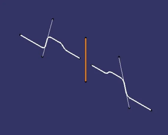
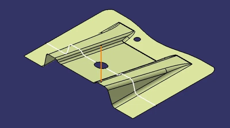
- The Center point of the hole in class-A was made and a plane is created at the point.
- Then intersection of the Class A & yz plane is created and the two inclined lines were
- Then bisector line of the two inclined lines is created, which is defined as the Tooling axis.
Procedure for Draft Analysis
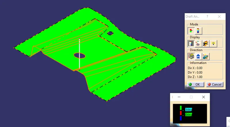
- The draft analysis tool is selected.
- Then by enabling compass the axis system is aligned in line with the tooling axis, to define the draft direction.
- Now the surface or part which should be subjected to draft analysis is selected.
- Lock Direction is applied that fixes the compass and then the mode dialog box is formed by snapping at any point on the part
- The Color Codes are classified and Draft Angles are applied
- Then the Running point analysis is used to hover around the part to analyze the permissible draft angles and the analysis is saved.
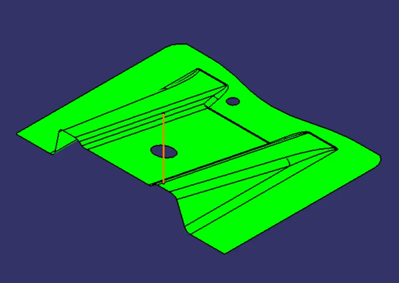
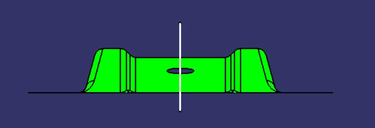
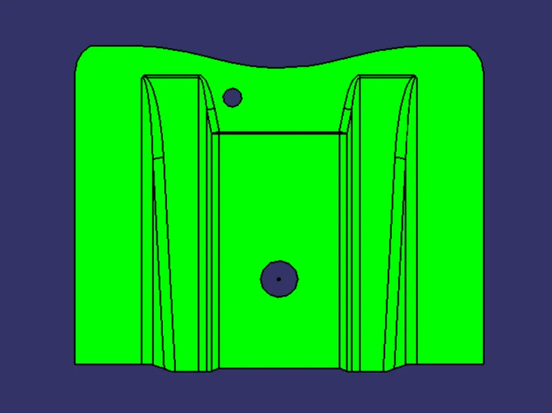
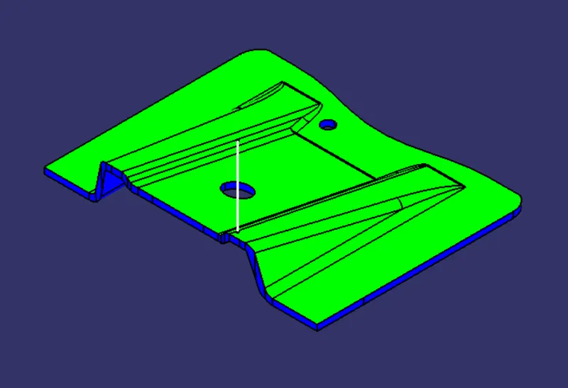
- This gives the result of the surfaces which have positive draft in green code.
Draft Analysis of Class A
Class B surface
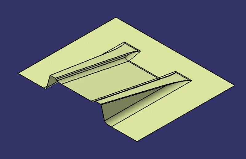
- For creating the class B surface the required surfaces from Class A are extracted and then untrimmed.
- Then all the surfaces have been extrapolated to get intersections between them and then trimmed.
- Since the thickness of the Base Bracket is 3 mm the trimmed surface was offset to 3 mm.
- Finally, the required corners have been filleted to finish Class B surface.
Class C surface
- The required boundaries of the Class A-Surface were extracted and smoothened.
- Then the curve swept with reference to the Tooling axis as draft direction with draft of 3deg.
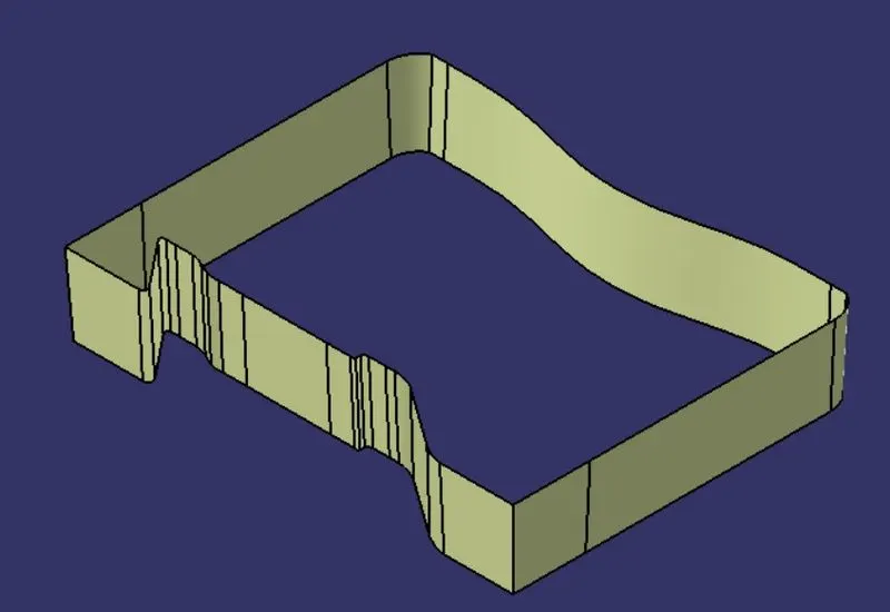
Final part
- Class A and Class C surfaces were joined together, and then trimmed with Class B surface to form a closed part.
- Then the closed part is made solid by Close Surface option to create the body of Base Bracket.
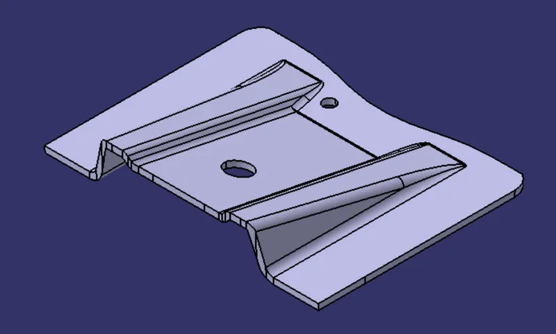
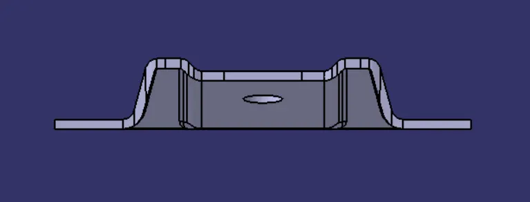
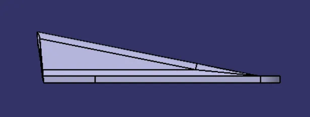
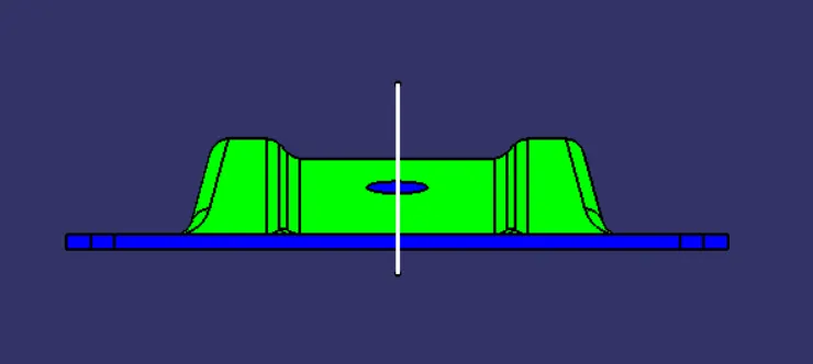
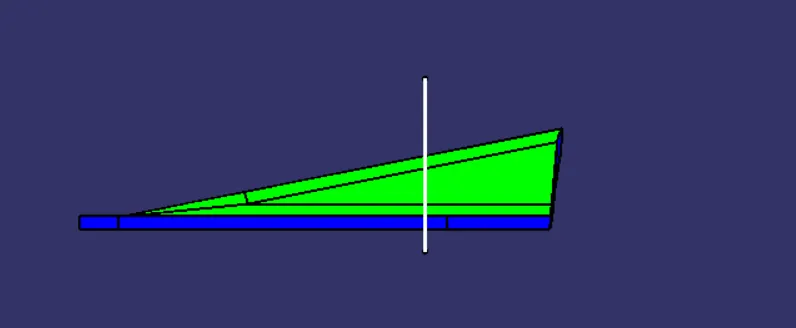
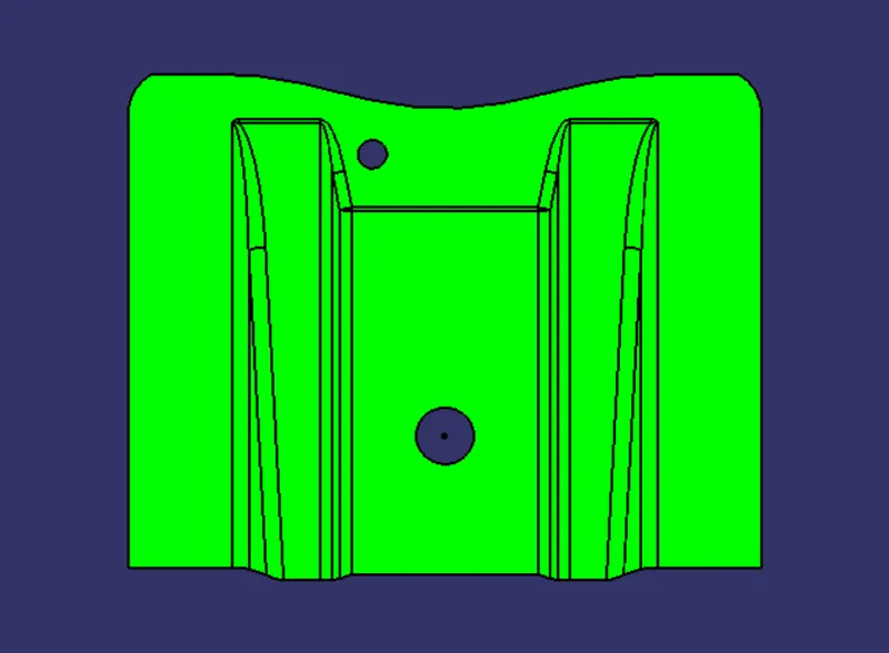
Draft Analysis of Base Bracket
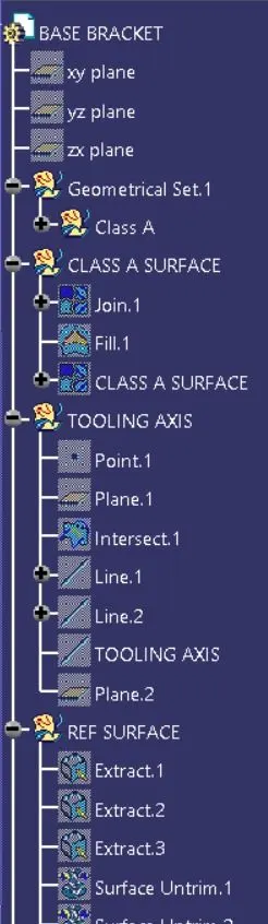
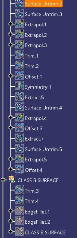
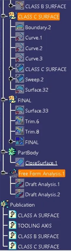
Feature tree & Publications
CONCLUSION
The Class B & Class C surfaces and the Tooling Direction have been created and Published and the Base Bracket part body is developed. Both the Class A surface and the Solid body have been successfully passed the Draft Analysis.