Week 8 - Challenge 1 - Base Bracket Design
AIM-
Create the Base Bracket Plastic component through the given Class-A surface. To begin with, the tooling axis for the given Class-A Surface should be created meeting the requirements of the draft angle and at the end perform the Draft analysis on the model.
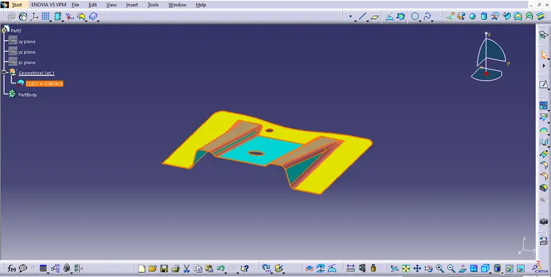
OBJECTIVES-
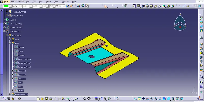
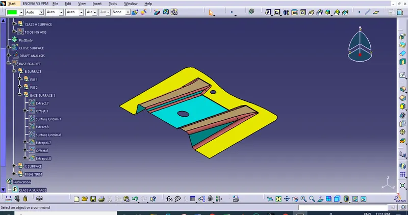
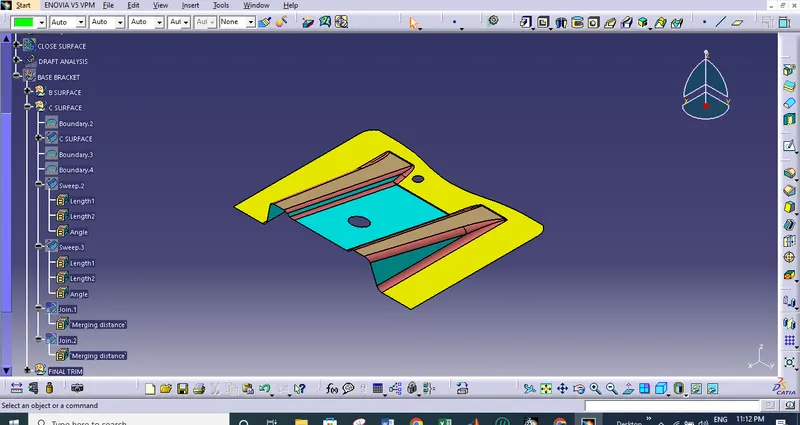
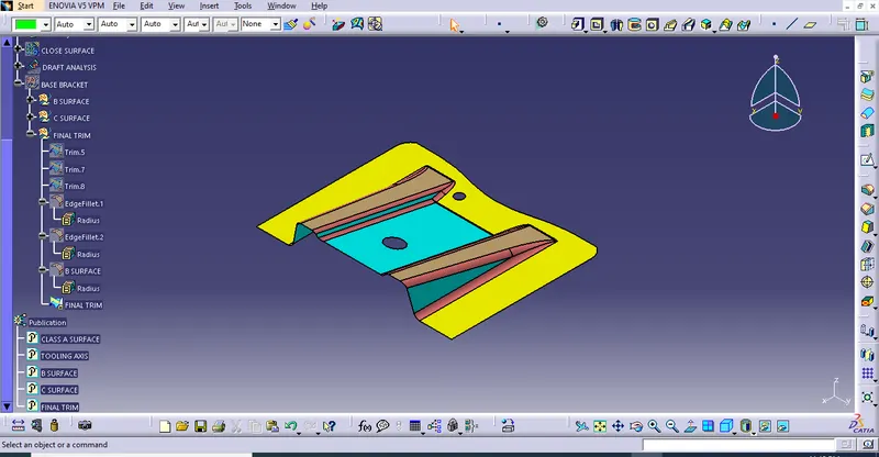
- Tree Structure
- Ensure Proper Tree Structure
- Geometrical sets should have a proper name based on the sketches present inside of it
- All the sketches should be created under the Geometrical set
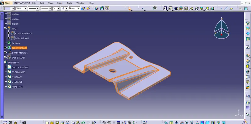
- Use the Close Surface feature to make a solid body from the surface.
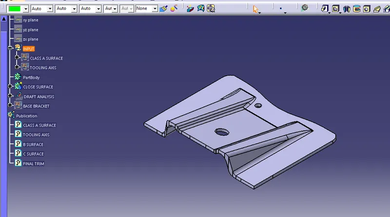
- Publications: Use the publication option and publish the below
- Tooling Axis
- Class A, B, and C surface
- Report
- A detailed report should be done explaining the draft analysis and the tooling axis creation.
- An explanation should be given on the way of creating the tooling axis, particularly the Bisecting method.
SOLUTION-
- Report-
A) A detailed report should be done explaining the draft analysis and the tooling axis creation.
Tooling axis creation-
1) By observing part or component we have to choose direction of drafting. while doing this we have to consider geomety of component. All holes, fillets, chamfer etc have to take in our consideration and we have to choose direction of drafting.
2) To start working on drafting process we have to choose middle portion of the component or if there is hole in component, we have to start from there.
3) Our first step is to create dummy axis. Now here we have created dummy axis with help of middle hole.
4) Now by observing component geometry, we have to choose direction or plane to create axis for bisecting the component. Here we have to consider geometry and also way in which drafting is become easy & it cover all parts of component.
5) By considering all above, we have to generate axis system or plan to bisect our component. After this we have to intersect plane or axis system with component. It will provide you one shape of geometry. Now we have to draw two lines from extreme outer two points of bisecting line or from extreme outer line.
6) By using line option, we have to create bisecting lines from those two final lines.Here in bisecting line option we have to choose correct line from horizantal or vertical line according to our drafting direction line.
7) This line will provide you final tooling axis line.
Draft analysis-
1) It is a tool that allows the user to ‘see’ whether the part they are designing can be removed from the tool being used to make it.
2)In the case of plastic injection molded parts it also allows the designer to see if there is enough draft on the part to ensure that it can be correctly grained.
3) we always use the tool with the axis direction method. Put the main axis on the draft direction line with Z being parallel to it. Select the tool then select the part body. You may need to reposition the axis again.
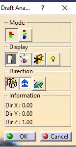
4) The results window has 2 options 1 with just 3 colour variants and the other with many variants. They can be edited by double clicking on them to give you the result you desire. The colours show the different draft angles.
5) We have to use following path for drafting anaylsis
Tools- Anaylsis- Feature draft anaylsis
6) At starting of drafting anaylsis we have to set compus which is show in direction row (2nd number option). During this w of compus is set towards the drafting angle.
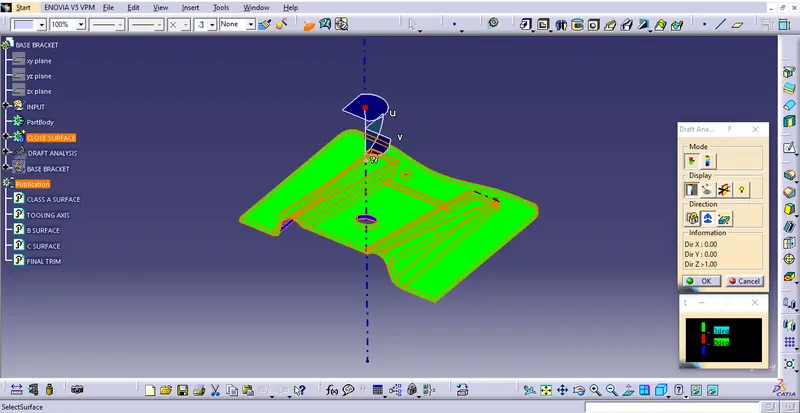
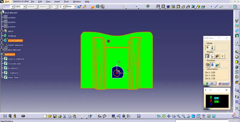
7)After this we have to click on component. Now component become green as shown in below image and also if it become blue then flip direction of compus using flip option in direction row.
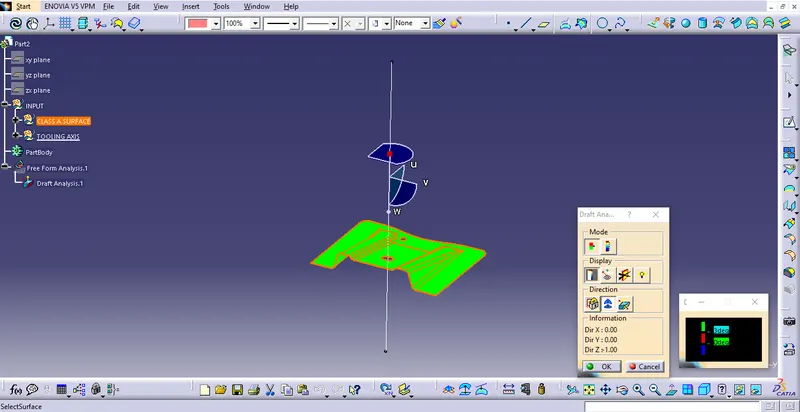
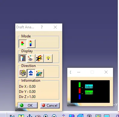
9) Finally set drafting angle at 3 degree and measure drafting angle at different faces of component by using display row.
10) If your component is green then drafting anaylsis process is completed.
B) An explanation should be given on the way of creating the tooling axis, particularly the Bisecting method.
1) By observing part or component we have to choose direction of drafting. while doing this we have to consider geomety of component. All holes, fillets, chamfer etc have to take in our consideration and we have to choose direction of drafting. In this case we have selected z axis for drafting direction.
2) we have selected middle whole for create dummy axis. In this whole we have add one point at center of hole and from this point we have create one line. We have consider this line as a dummy axis.
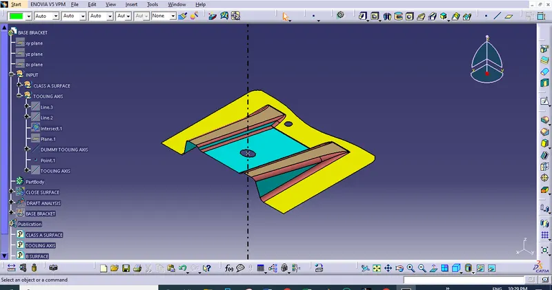
3) Now by observing component geometry, we have to choose direction or plane to create axis for bisecting the component. Here we have choose zy plane or y direction and generate plane parellel to zy plane with respect to center point of hole.
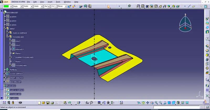
4) After this we have to intersect plane or axis system with component. It will provide you one shape of geometry.
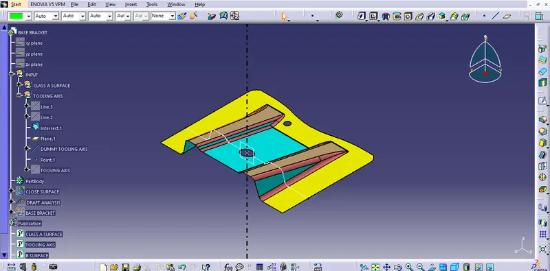
5) Now we have to draw two lines from extreme outer two points of bisecting line or from extreme outer line.
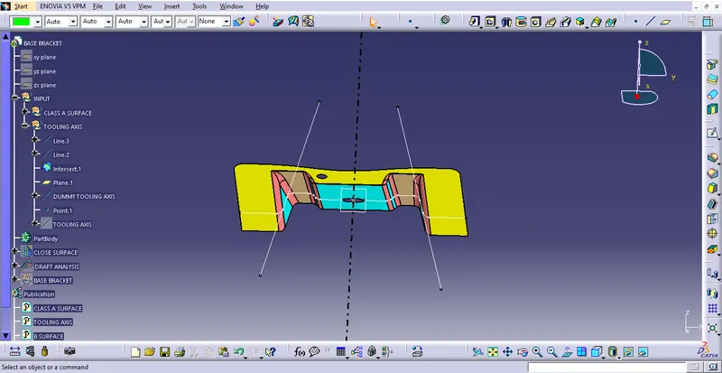
6) By using line option, we have to create bisecting lines from those two final lines.Here in bisecting line option we have to choose correct line from horizantal or vertical line according to our drafting direction line.
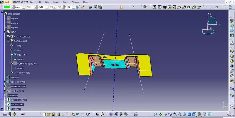
7) This line will provide you final tooling axis line.
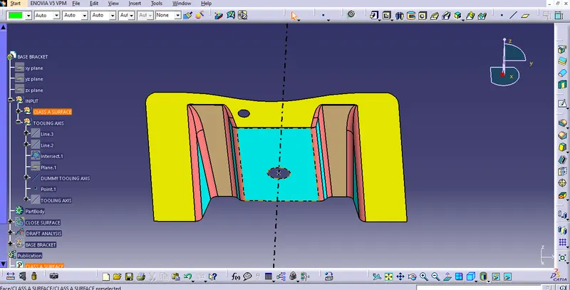
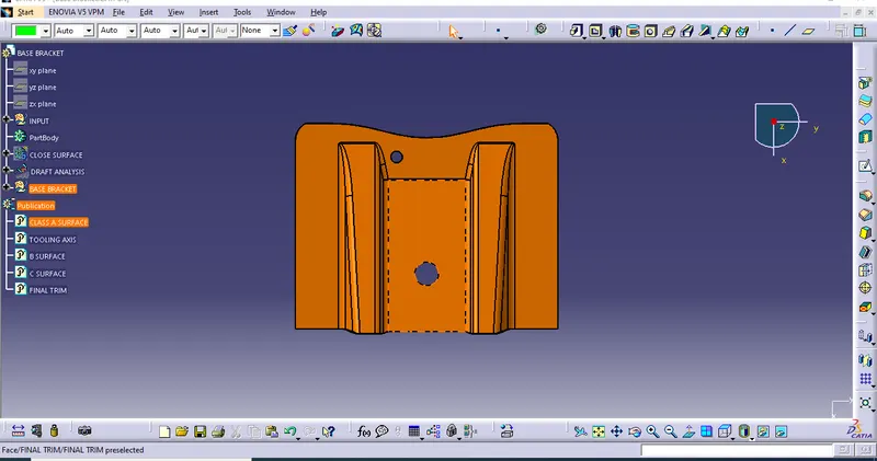
- Tree Structure:-
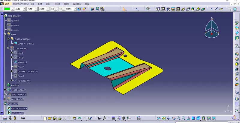
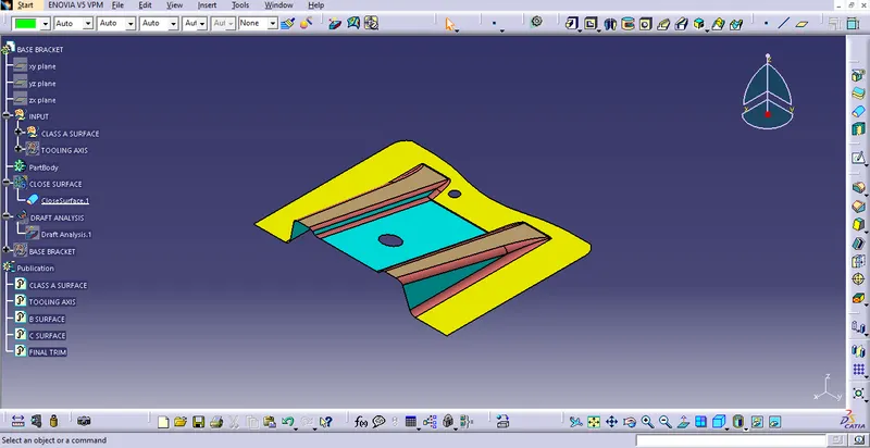
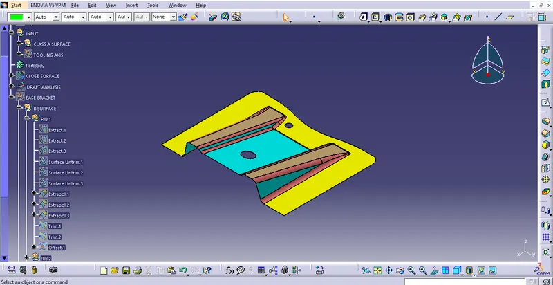
Close Surface:-
- Publications: Use the publication option and publish the below
- Tooling Axis
- Class A, B, and C surface
- Screenshots of the Draft analysis report for both the given Class-A surface and the final plastic component
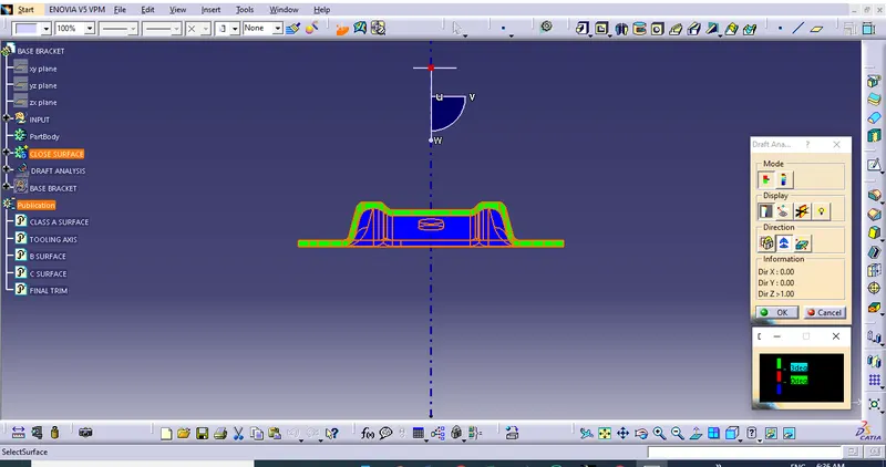
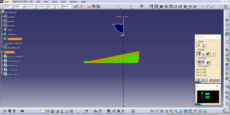
DRAFT ANALYSIS REPORT FOR CLASS A SURFACE
DRAFT ANALYSIS REPORT FOR FINAL PLASTIC COMPONENT
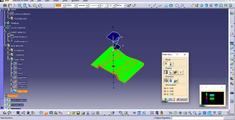
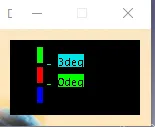
- with the proper color code of the draft angle in various orientations (Isometric, Front, Side, and Top View)
ISOMETRIC VIEW-
FRONT VIEW-
SIDE VIEW-
TOP VIEW-
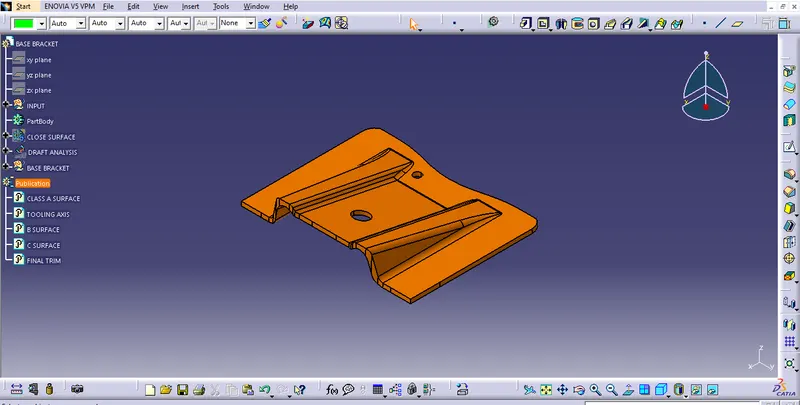
Screenshots of the plastic model in various orientations (Isometric, Front, Side, and Top View)
ISOMETRIC VIEW-
FRONT VIEW-
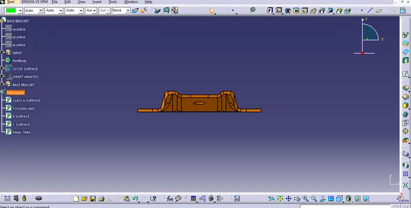
SIDE VIEW-
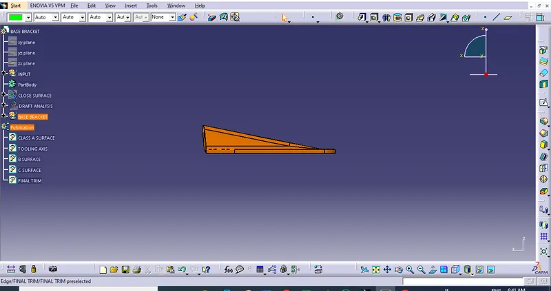
TOP VIEW-
CONCLUSION-
Base Bracket Plastic component through the given Class-A surface is created by using tooling axis for the given Class-A Surface. Drafting analysis for both plastic and solid component has been done.