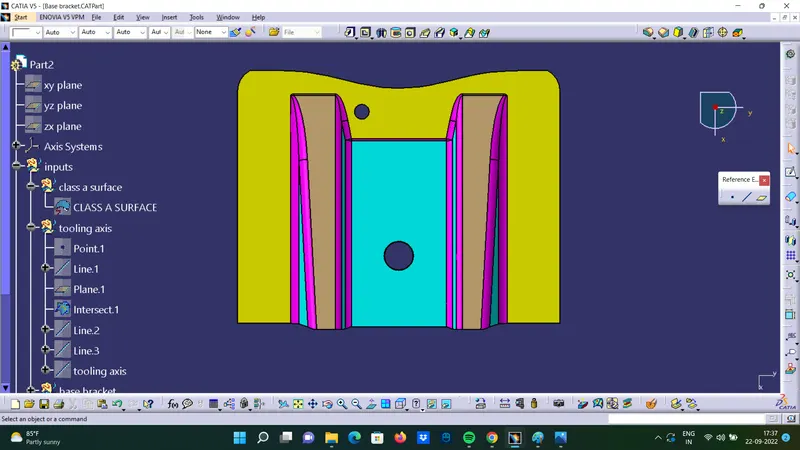
Week 8 - Challenge 1 - Base Bracket Design
Base Bracket Design
DRAFT ANALYSIS:
To perform draft analysis, click on Insert >>Analysis >> Feature Draft Analysis
Once the draft analysis toolbar is opened, go to the display block and select the 'Analysis under the running point' command to check the angle for different sides (ribs and inclined plane angles) on the class A surface. The color scale on the bottom visualizes, whether the draft angle meets the requirements or not (3 deg) by indicating the colors Green, Blue and Red. Once the draft angle analysis was done, we need to align and fix the compass to the tooling axis of the class A surface.
To align and fix the compass to the tooling axis, go to the Direction block in the draft analysis toolbar and click on the 'Use the compass to define the new current draft direction option (or just click on the compass symbol). Now bring the compass to the surface and align it to the tooling axis of the class A surface and click on the lock symbol beside the compass in the direction block. Once we click on 'ok' on the draft analysis toolbar, we can finish the draft analysis process.
Image of the complete Draft analysis and the color scale variant
Draft analysis report of Class-A surface-
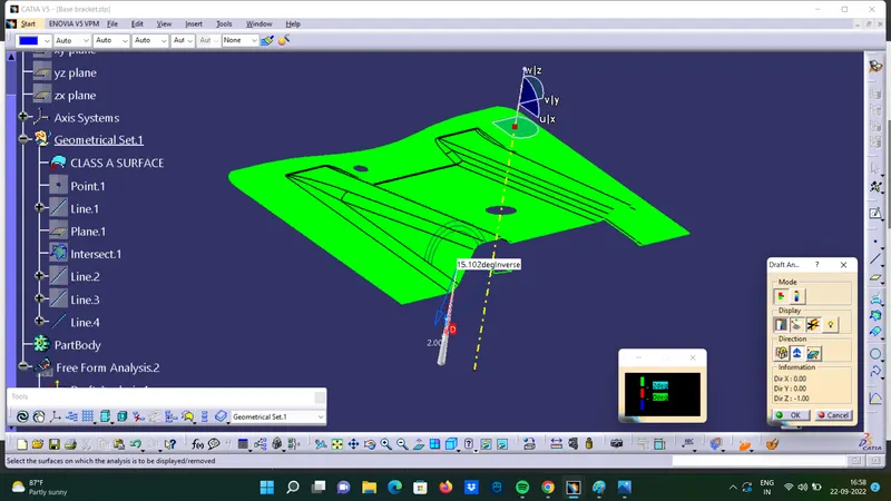
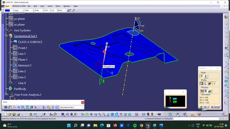
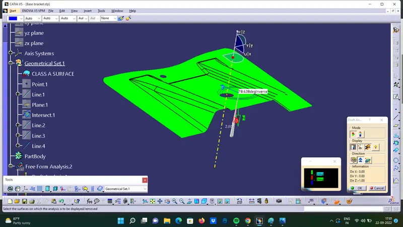
Draft analysis report of final plastic component-
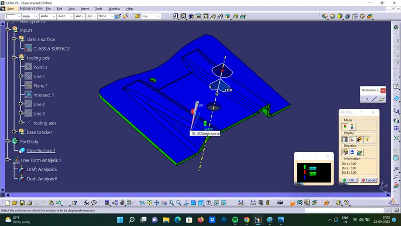
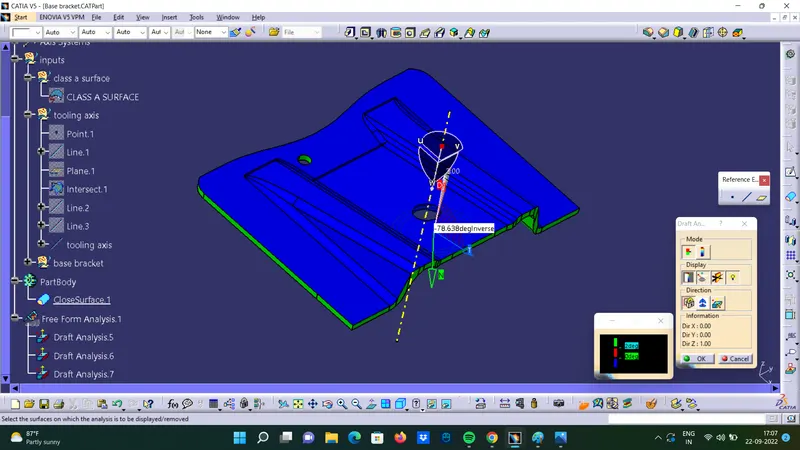
Tooling axis creation
The tooling axis is the direction of drawing a sheet metal where the finished component is easily ejected on a particular direction and axis. The tooling axis is important for removing the material when finished.
Creation of tooling axis (bisecting method)
Step 1:
Identify the required and most perfect plane which is suitable for creating a tooling axis.
the XY plane is most suitable for the creation of the tooling axis.
Step 2:
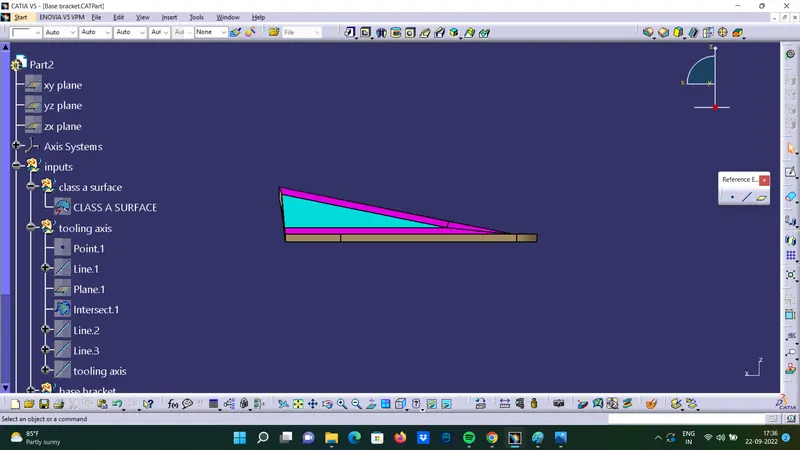
Create a dummy axis that will be used until creating an original tooling axis. And then take reference curve by taking a section from the ZX plane and using those boundary curves for creating a bisecting curve and that curve will be the tooling clearing for x-direction.
Step 3:
after creating the actual axis curve we can now perform the draft analysis on the given class-A surface. before performing the analysis change material property to customizable view parameters.
solid model
Isometric View
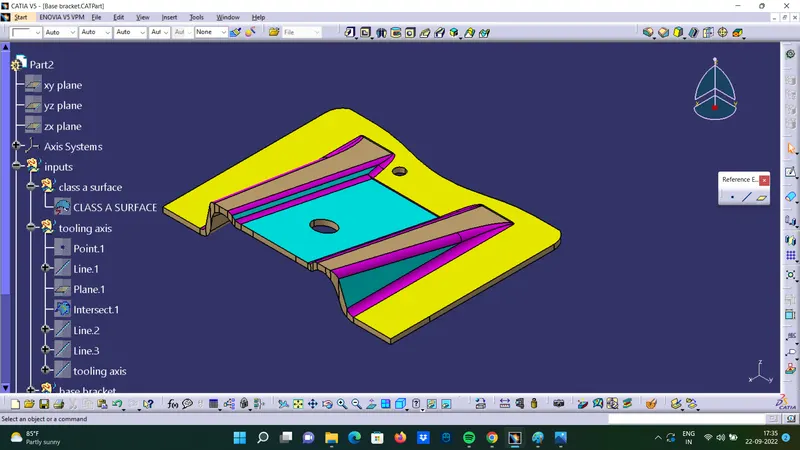
Front View
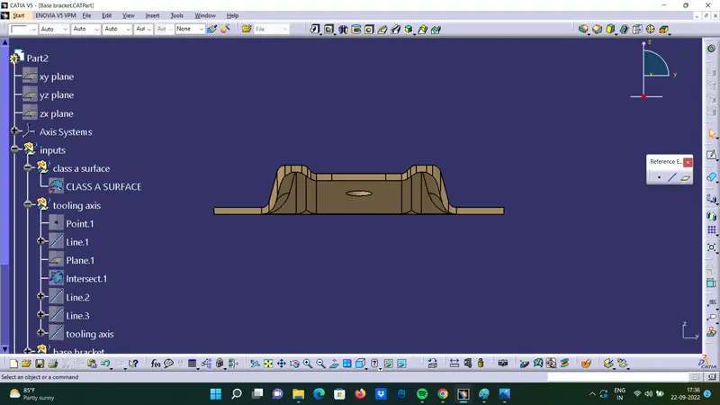
Side View
Top View