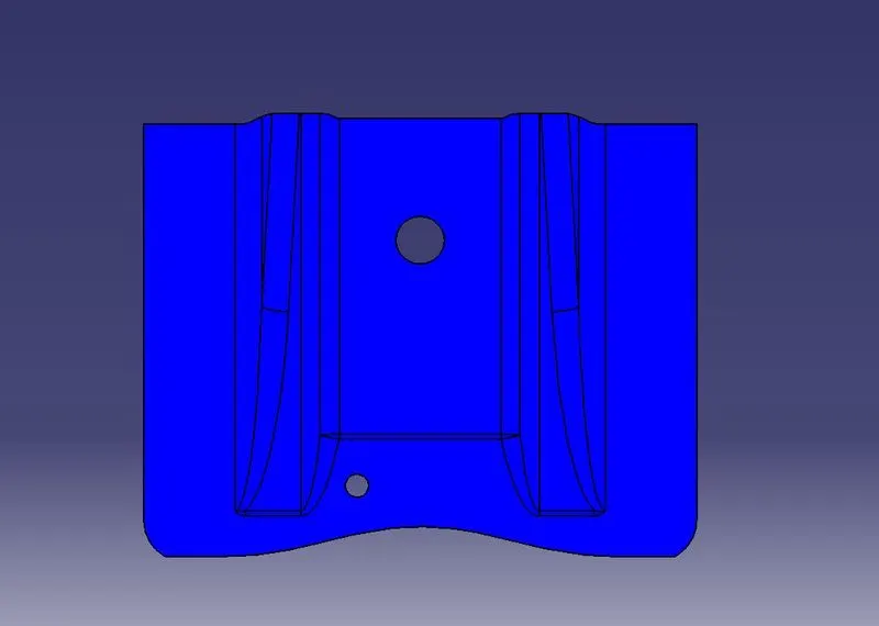
Week 8 - Challenge 1 - Base Bracket Design
BASE BRACKET DESIGN CHALLENGE
Introduction-: To design the base bracket plastic component following all the design standards and intents regard to manufacturing prpcesses. Also perform the draft analysis for component.
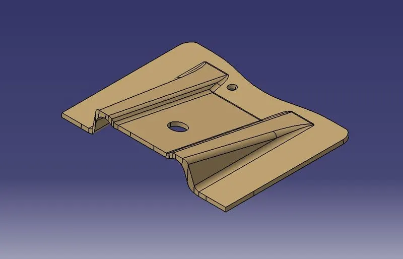
BASE BRACKET
Objective-:
1. To design the part with all the standards taking into consideration.
2. Using Class-A surface to design the component.
3. Ensure the proper tree structure.
4. To create the tooling axis.
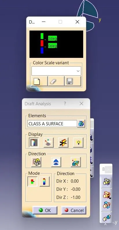
5. To perform the draft analysis of Class-A & component.
Draft Analysis-:
1. Class-A Surface-:
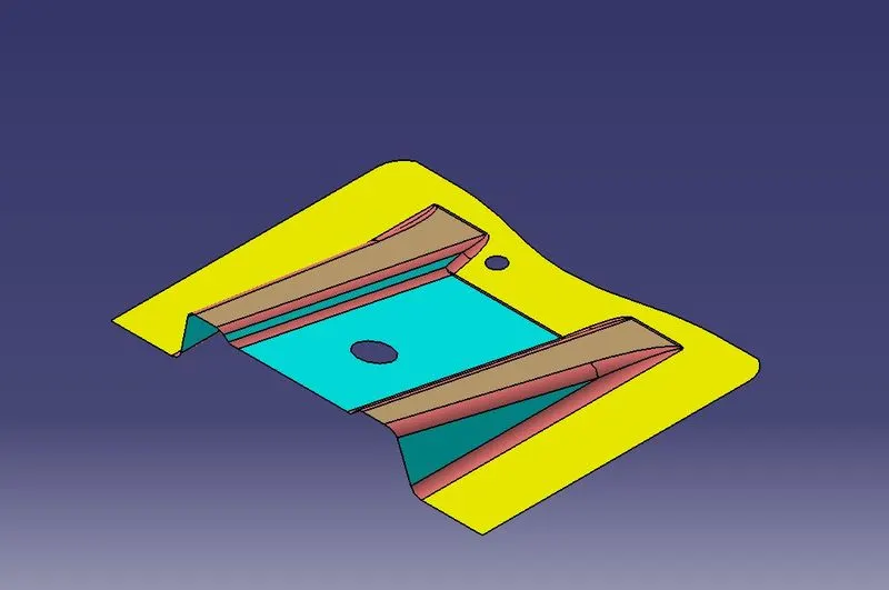
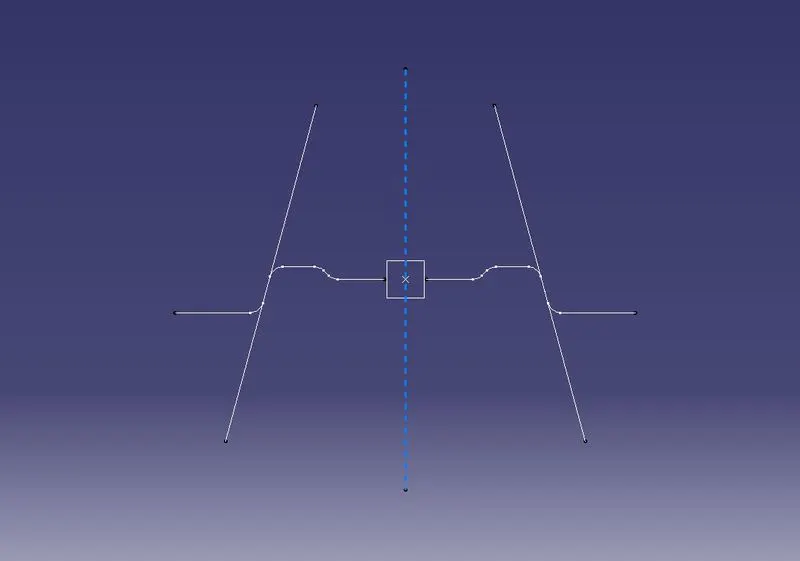
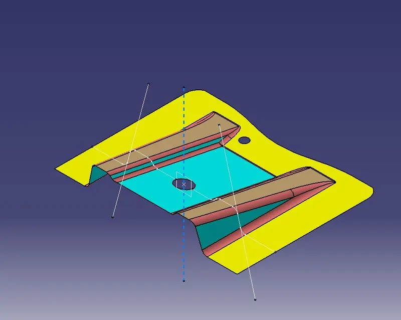
2. Tooling Axis-: The tooling Axis for the component is determmined by analysing the Class-A surface. The surface is then intersected along the YZ plane to determine the section view of the surface along the YZ plane. The lines are drawn into the complex sections which are needed to be analysed for the draft angle and tool axis.
Then a bisecting line is created for the two drawn lines this is the required tooling axis for the component in Z axis.
The tooling axis is illustrated below in figure for your reference.
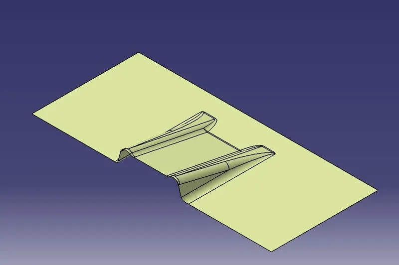
3. Class-B Surface-: Then using the Class-A surface the Class-B surface is developed using the surface workbench. The Class-B Surface is the surface that is constructed in respect to the given inputs as per the Class-A surface.
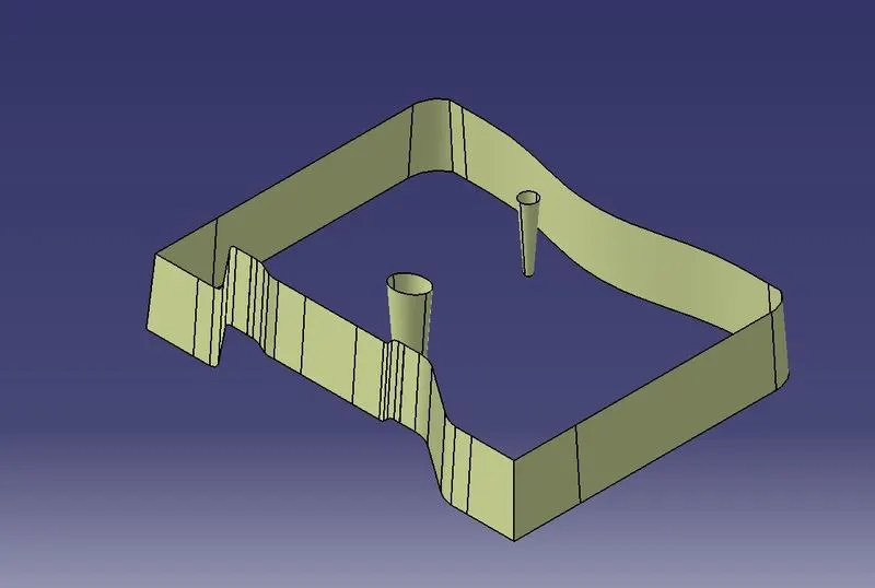
4. Class-C SUrface-: Class C surface is the surface that is the side walls of the components that are drafted for proper component ejection during the manufacturing process.
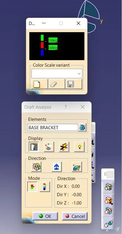
5. Draft Analysis-:
a. Class-A Surface-:
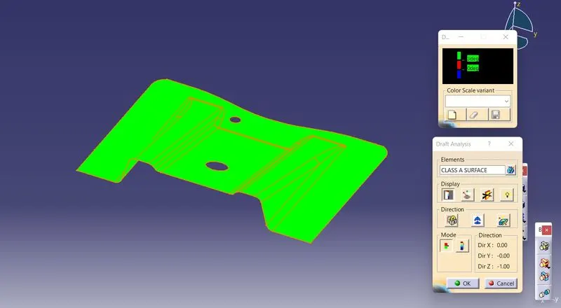
Color Scale-:
b. Component-:
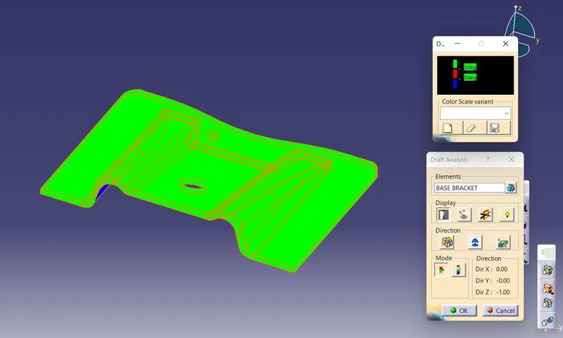
Color Scale-:
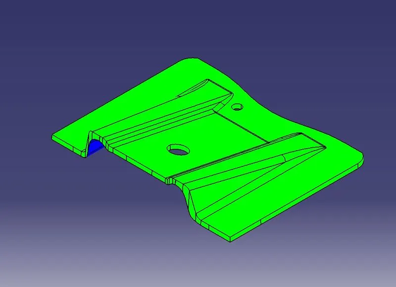
6. Part/Component in different orientations & views-:
a. Isometric View-:
b. Front View-:
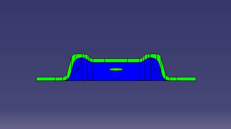
c. Left View-:
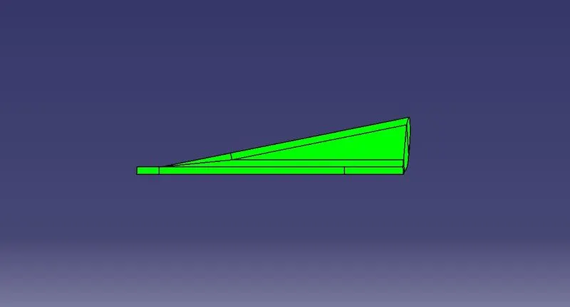
d. Top View-:
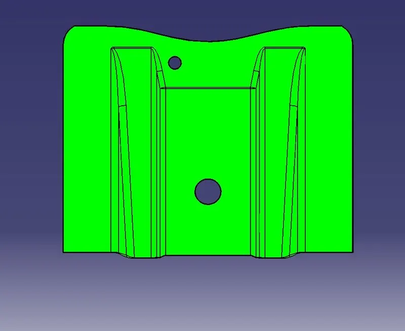
e. Bottom View-: