Week 8 - Challenge 1 - Base Bracket Design
AIM
Create the Base Bracket Plastic component through the given Class-A surface. To begin with, the tooling axis for the given Class-A Surface should be created meeting the requirements of the draft angle and at the end perform the Draft analysis on the model.
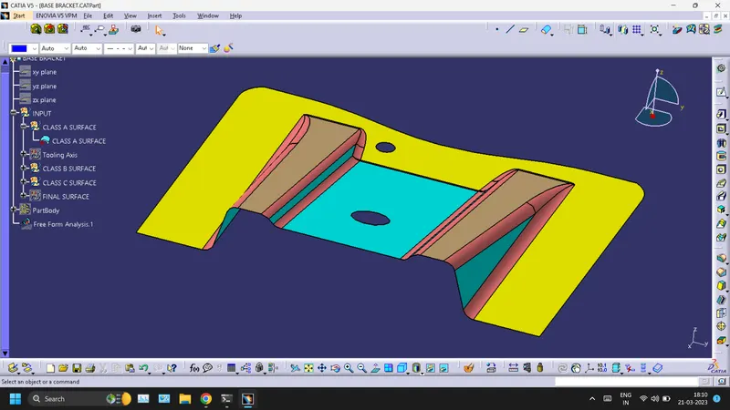
CLASS A SURFACE
TOOLING AXIS CREATION
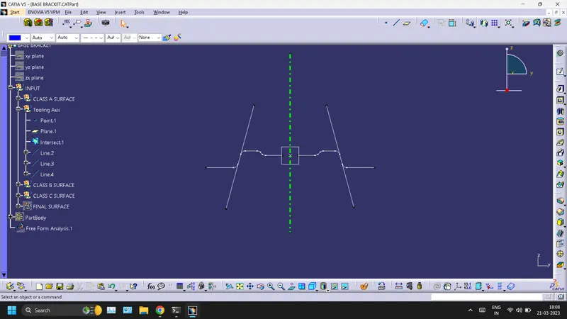
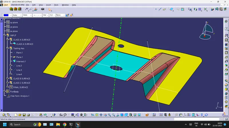
- Create an intersection of CLASS A surface with ZX plane and from the intersection create the tooling axis as shown below.
- Create a bisecting line using the lines shown above.
CLASS B SURFACE
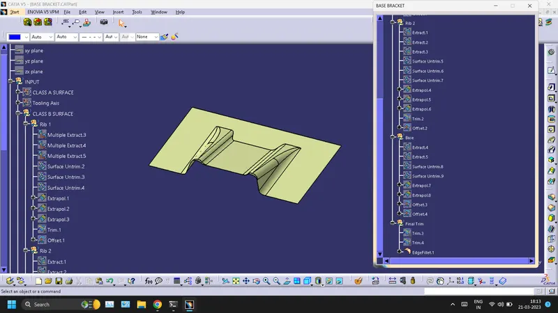
To create the class B surface, I considered the entire surface has 3 parts 'Rib-1, Rib-2, and Base surface'. If we directly offset the class A surface, fillets may lead to cause an error, to avoid the errors we need to extract the surfaces and untrim the extracted surfaces and extrapolate those untrimmed surfaces with point continuity. Now trim those extrapolated surfaces to the required shape. And finally, fillets were given to the final trim
CLASS C SURFACE
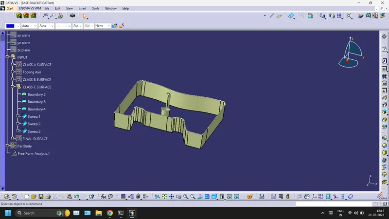
- For creating this surface we have extracted the boundry of Class A using multi-extract and then converted to smooth curve. Now this smooth curve is swept along the draft direction with a 3deg draft.
FINAL SURFACE WITH A, B, AND C SURFACE
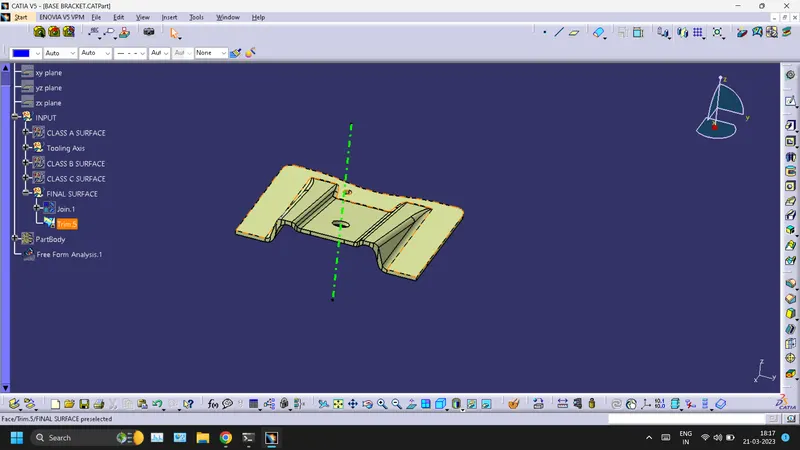
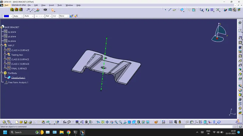
PART BODY OF BASE BRACKET (CLOSED SURFACE)
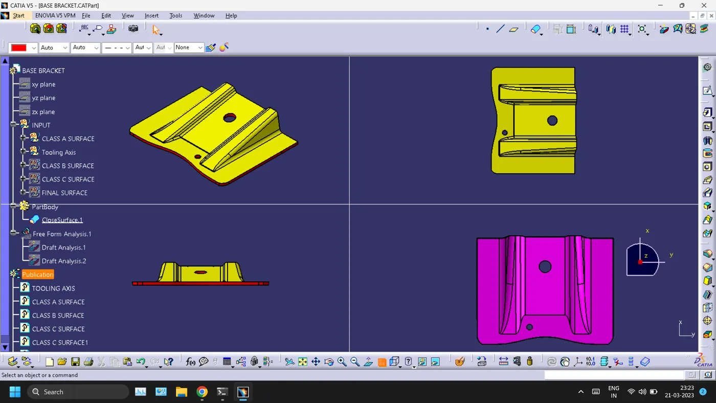
DRAFT ANALYSIS
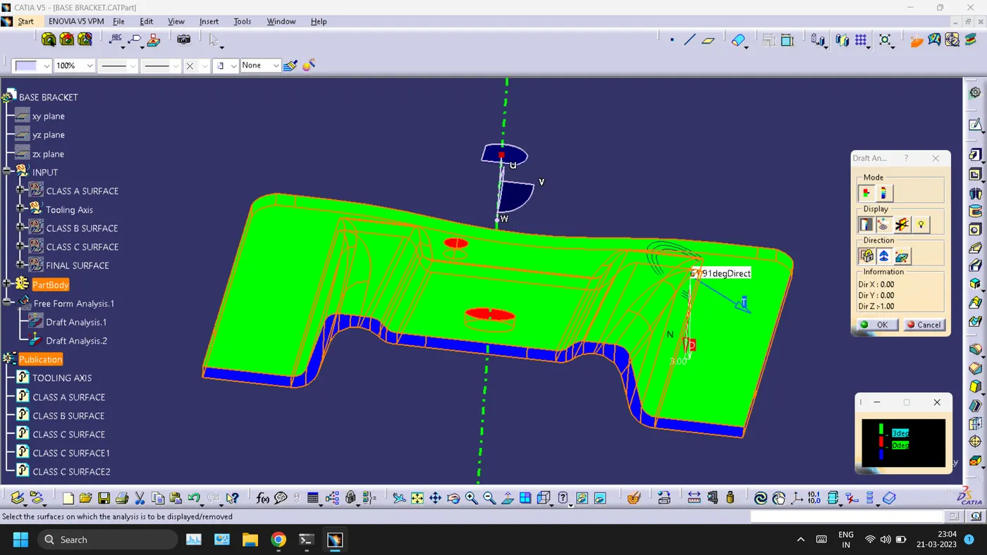
- A-SURFACE
The analysis is done for the 3degree draft. So as can be seen all the surfaces are more than 3deg. 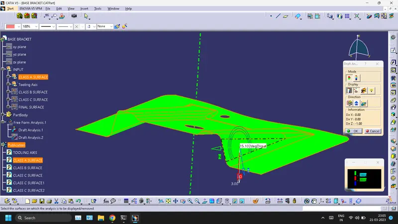
- BASE BRACKET FULL BODY
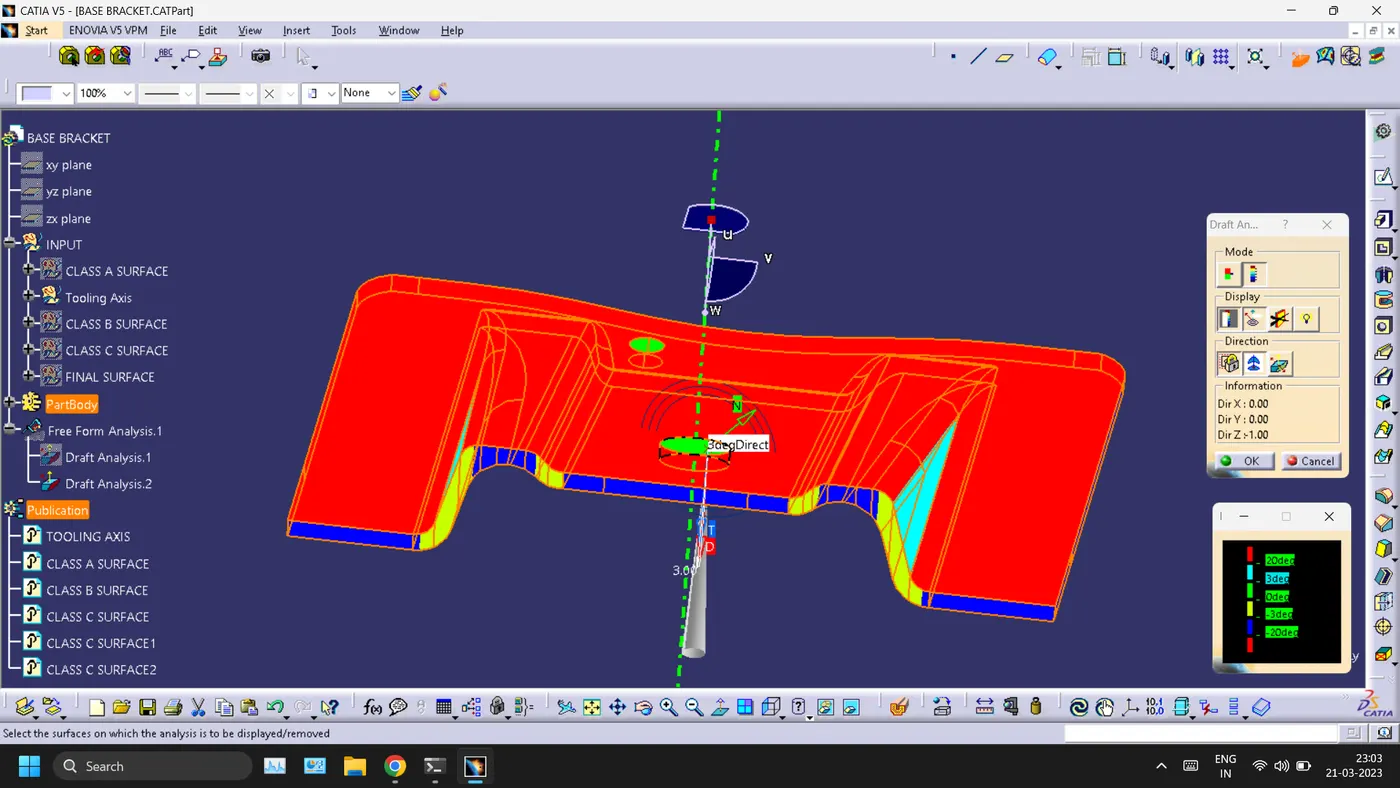
For this analysis, the main tooling axis is taken draft reference.
The following results were obtained