Week 8 - Challenge 1 - Base Bracket Design
Aim:- To Create the Base Bracket Plastic component through the given Class-A surface. To begin with, the tooling axis for the given Class-A Surface should be created meeting the requirements of the draft angle and at the end perform the Draft analysis on the model.
Tooling Axis:-
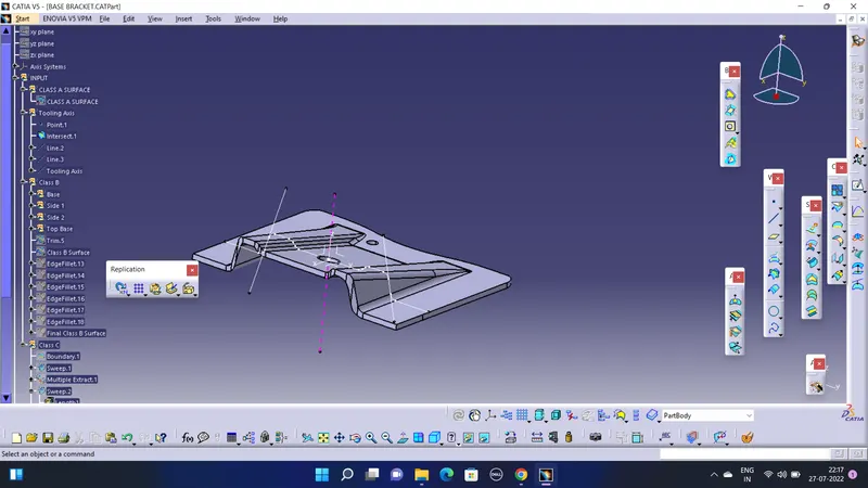
There are Two Ways to take a tooling axis, first is to take a line normal to a surface extracted along the ejection direction.
The second way is shown Above, The two reference lines are taken with respect to the tapper surface and a bisecting line to bother the reference lines pacing through a point is taken as a Tooling axis so that the draft given can be smoothly taken out while ejecting the part.
Draft Analysis:-
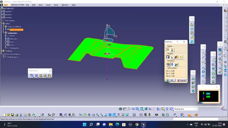
On Class A surface:-
On Final Plastic Part:-
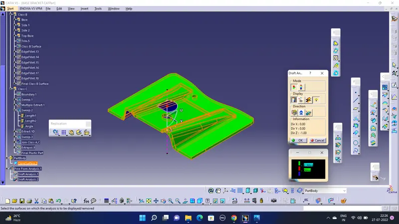
Geometrical sets and part Body :-
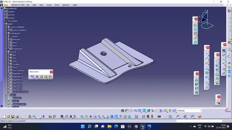
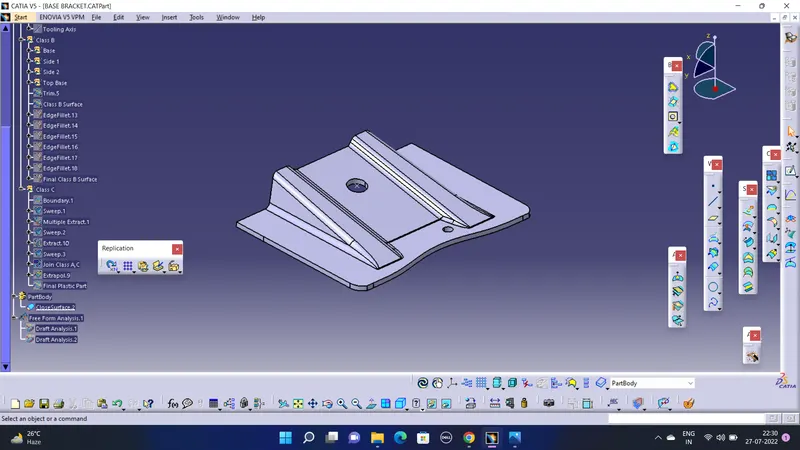
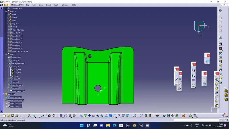
- Screenshots of the solid model with the proper color code of the draft angle in various orientations (Isometric, Front, Side, and Top View)
Isometric View:-
Front View:-
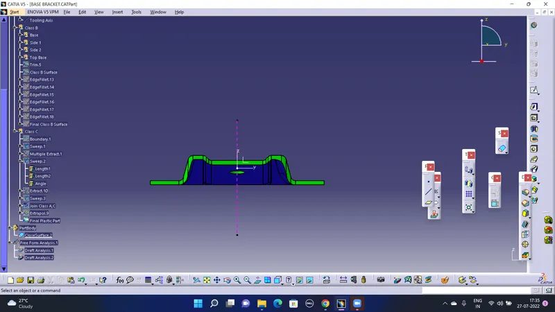
Side View:-
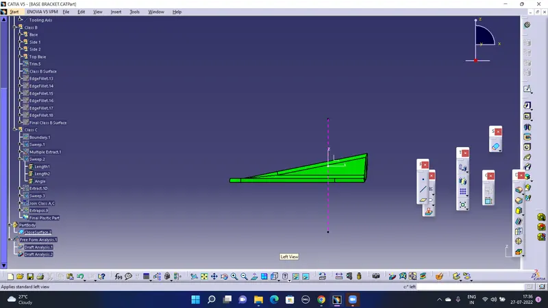
Top View:-