Week 8 - Challenge 1 - Base Bracket Design
Week 8 - Challenge 1 - Base Bracket Design
Q. Create the Base Bracket Plastic component through the given Class-A surface. To begin with, the tooling axis for the given Class-A Surface should be created meeting the requirements of the draft angle and at the end perform the Draft analysis on the model. The Thickness of Plastic Part should be considered as 2.5 mm.
NOTE:
- Geometrical sets should have a proper name based on the sketches present inside of it
- All the sketches should be created under the Geometrical set
- Use the Close Surface feature to make a solid body from the surface.
Report
A detailed report should be done explaining the draft analysis and the tooling axis creation.
An explanation should be given on the way of creating the tooling axis, particularly the Bisecting method.
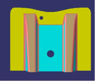
Given Class 'A' Surface:
Steps Followed After Receiving Class-A surface:
Check the surface's connectivity using joins and boundaries commend, and make sure there are no gaps between the surfaces. Then define the tooling axis of the given surface after checking connectivity.
1.Tooling Axis:
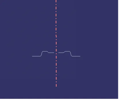
- The direction in which the mould open and closes is the tooling axis.
- The mould is built from two separatebody i.e., Core and Cavity, and tooling direction basically defines the direction of mould pulls apart.
- Basically Tooling axis should be determined in flat length surface or surface having Hole on it. Create a point and use line command and drwa a dummy tooling axis
2.Bisecting Line:
Identify a plane where we are going to do more operations and using intersection command.
- Take profile which will create a problem and extend the profile using line command.
- Then create the bisecting line between the two lines and that will be taken as tooling axis.
3.Draft Analysis:
- Draft is required on all parts in the direction of mold movement in order to allows parts to realease or eject from the mold properly.
- Draft is the angle in which the parts is tapered to allow it to realease. As the part cools it tend to shrink to the core side of the mold.
- Adding draft helps to release, most parts require a minimum of 1/2 to 1 deg, however 3 degree is widely accepted as the norm for the plastic components.
Class 'B' Surface:
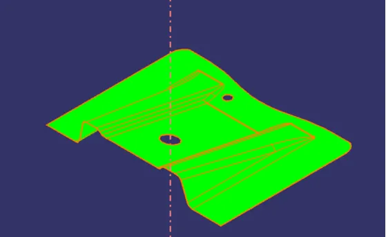
- Initially extract the both ribs surface of the class A surface and untrim the surfaces.
- And extrapolate the surface for the required dimensions and offset the surface to 2.5mm same as thickness.
- Trim the surfaces which are not required
- Do the same for the base surfaces and trim with both rib surfaces for the required shapes.

Class C Surface:
Extract the outer boundary of the Class-A surface and create the Class 'C' surface with the Sweep command.
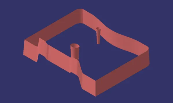
Final Solid :
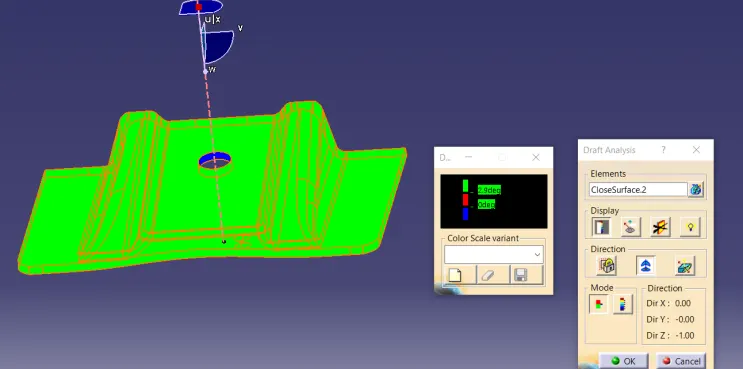
Draft Analysis of the Final Solid model with the draft angle 2.9 ( just below the 3 deg):