Week 8 - BlockMesh Drill down challenge
Problem Definition
We are going to simulate an incompressible-laminar-viscous flow through the backward facing step geometry. We should perform a transient simulation. The solver can be chosen based on the described physics of the flow. We need to explain the entire simulation procedure (how we set up the case). We should also provide explanations to every change we make inside the reference case files obtained from OpenFOAM tutorials. We need to find out:-
1. How does the velocity magnitude profile change as a function of mesh grading factor? (factors, 0.2, 0.5, 0.8)
2. Measure the velocity profile at 0.085 m from the inlet of the geometry?
3. Compare velocity magnitude contours near the step region for the above mentioned grading factors.
Mesh Specification
- Number of cells along the x direction (longer dimension) = 200
- Number of cells along the y direction = 10
- Use a graded mesh. Grading factor near all walls should be 0.2
Introduction
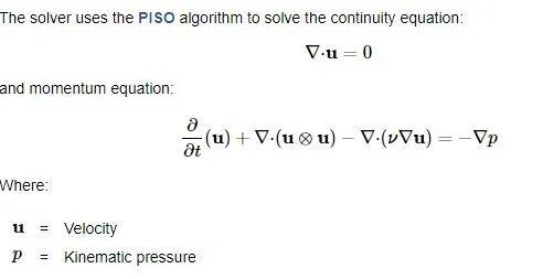
We are simulating an incompressible-laminar-viscous-transient flow through the backward facing step geometry. Because of this flow of nature, we are going to choose icoFoam solver.
We are going to solve the following equations:-
BlockMesh
We need to create the following geometry:-
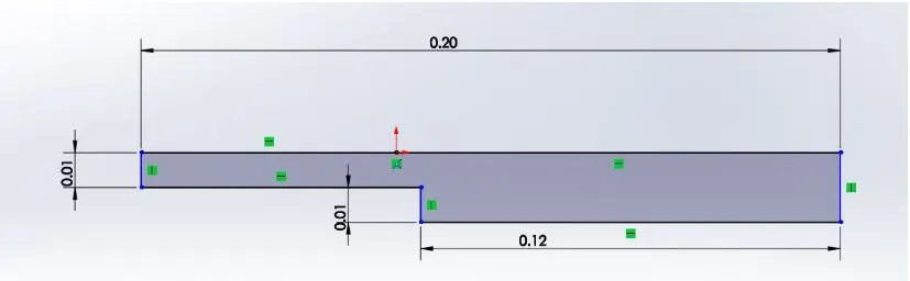
To create the geometry as shown in figure, We are going to use blockMeshDict file available in the system.
Geometry Creation
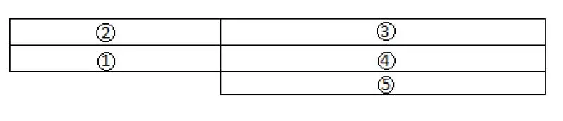
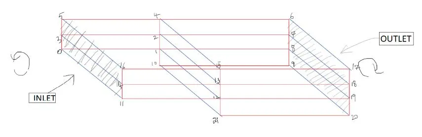
To create the geometry we are going to use 5 blocks.
Now we are going to indexing the vertices on the back side of the blocks and than front side of the blocks. We are going to start index from 0 because openFoam uses C++ programming.
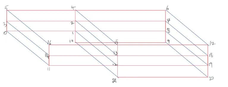
Now we are going to define the blocks. We need to be careful while defining the blocks. We need to specify the right order of vertex indices.
For example to create the first block
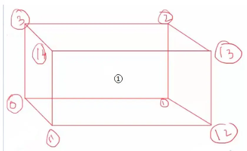
we need to use this command
hex(0 1 2 3 11 12 13 14)(1 1 1)simplegrading(1 1 1)
In the above command '(0 1 2 3 11 12 13 14)' are the block vertices, '(1 1 1)' are the number of grid points in x, y and z-direction respectively and 'simplegrading(1 1 1)' are the grading of the x, y and z-direction grid points.
Each block of the geometry is defined by 8 vertices, one at each corner of a hexahedron. The vertices are written in a list so that each vertex can be accessed using its label
So like this we are going to create all the blocks and create the mesh.
Boundary Conditions
1. Inlet
We have 2 faces contributing to the inlet boundary condition. If we looks at the face from the outside, the definition of the face will be in counter-clockwise direction. Inlet is of patch type. The patch type is type for a patch condition that contains no geometric or topological information about the mesh.
(0 11 14 3)
(3 14 16 5)
2.Outlet
We have 3 faces contributing to the outlet boundary condition. If we looks at the face from the outside, the definition of the face will be in counter-clockwise direction. outlet is of patch type. The patch type is type for a patch condition that contains no geometric or topological information about the mesh.
(9 8 19 20)
(8 7 18 19)
(7 6 17 18)
3.Front & Back
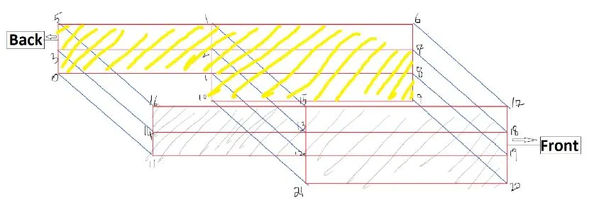
We have the five faces in the front and 5 faces at the back side. We are looking at the back side face from the inside so the definition of the face will be in clockwise direction and counter-clockwise direction for the front faces. Front and back face are the empty type. Our geometry is in 3 dimensions. But we are solving in 2 dimension. So we are specifying the empty condition on each patch whose plane is normal to the 3rd (and 2nd) dimension for which no solution is required.
(3 2 1 0)
(5 4 2 3)
(1 8 9 10)
(2 7 8 1)
(4 6 7 2)
(11 12 13 14)
(14 13 15 16)
(21 20 19 12)
(12 19 18 13)
(13 18 17 15)
4.Fixed walls
Now we are going to define the fixed walls(top and bottom). We have the five faces which are the wall type.
There are instances where a patch that coincides with a wall needs to be identifiable as such, particularly where specialist modelling is applied at wall boundaries.
(16 15 4 5)
(15 17 6 4)
(10 21 12 1)
(0 1 12 11)
(10 9 20 21)
OpenFoam Script
1. First open the open the Linux Operating system.
2. Now type 'tut' and press enter. It will takes you to the in-built tutorial files. Now type 'ls' to check the files in this folder.
3. We are solving the incompressible problem. So we are going to the incompressible folder by the 'cd incompressible' command. It takes you to the incompressible directory.
4. Now type 'cd icoFoam' that takes you to the icofoam directory. In this directory there are two folder elbow and cavity.
5. Now we are going to copy cavity file by 'cp -r cavity/ $FOAM_RUN'. This will copy all the cavity file and paste it in the run folder.
6. Now type 'run' it will take you to the run folder. Now type ls to check the files in that folder. There we will find cavity folder. Now open that folder. There an another folder name 'cavity'. Now open that folder by 'cd cavity'.
7. Now we are going to type 'cd system' it will take you to the system directory. now when we type 'ls' it shows what is in this directory.
8. Now we are going to create Mesh for our problem in the blockMeshDict. So in order to edit that we are going to use 'gedit blockMeshDict'. It will open the text editor file.
9. so we does the following edit in the editor:-
blockMeshDict
/*--------------------------------*- C++ -*----------------------------------*\
  =========                 |
  \\      /  F ield         | OpenFOAM: The Open Source CFD Toolbox
   \\    /   O peration     | Website:  https://openfoam.org
    \\  /    A nd           | Version:  8
     \\/     M anipulation  |
\*---------------------------------------------------------------------------*/
FoamFile
{
    version     2.0;
    format      ascii;
    class       dictionary;
    object      blockMeshDict;
}
// * * * * * * * * * * * * * * * * * * * * * * * * * * * * * * * * * * * * * //

convertToMeters 1;

vertices
(
    (0 0 0) //0
    (0.08 0 0) //1
    (0.08 0.005 0) //2
    (0 0.005 0) //3
    (0.08 0.01 0) //4
    (0 0.01 0) //5
    (0.2 0.01 0) //6
    (0.2 0.005 0) //7
    (0.2 0 0) //8
    (0.2 -0.01 0) //9
    (0.08 -0.01 0) //10
    (0 0 0.05) //11
    (0.08 0 0.05) //12
    (0.08 0.005 0.05) //13
    (0 0.005 0.05) //14
    (0.08 0.01 0.05) //15
    (0 0.01 0.05) //16
    (0.2 0.01 0.05) //17
    (0.2 0.005 0.05) //18
    (0.2 0 0.05) //19
    (0.2 -0.01 0.05) //20
    (0.08 -0.01 0.05) //21
);

blocks
(
    hex (0 1 2 3 11 12 13 14) (80 5 1) simpleGrading (1 1 1)
    hex (3 2 4 5 14 13 15 16) (80 5 1) simpleGrading (1 1 1)
    hex (10 9 8 1 21 20 19 12) (120 10 1) simpleGrading (1 1 1)
    hex (1 8 7 2 12 19 18 13) (120 5 1) simpleGrading (1 1 1)
    hex (2 7 6 4 13 18 17 15) (120 5 1) simpleGrading (1 1 1)
);

edges
(
);

boundary
(
  inlet
    {
        type patch;
        faces
        (
            (0 11 14 3)
            (3 14 16 5)

        );
    }
  outlet
    {
        type patch;
        faces
        (
            (9 8 19 20)
            (8 7 18 19)
            (7 6 17 18)
        );
     }
    fixedWalls
    {
        type wall;
        faces
        (
            (16 15 4 5)
            (15 17 6 4)
            (10 21 12 1)
            (0 1 12 11)
            (10 9 20 21)
        );
    }
    frontAndBack
    {
        type empty;
        faces
        (
            (3 2 1 0)
            (5 4 2 3)
            (1 8 9 10)
            (2 7 8 1)
            (4 6 7 2)
            (11 12 13 14)
            (14 13 15 16)
            (21 20 19 12)
            (12 19 18 13)
            (13 18 17 15)
        );
    }
);

mergePatchPairs
(
);

// ************************************************************************* //
Explaination
- We are giving the co-ordinance in the meter already. So we will use convertToMeters to be 1.
- Now we are going to define the vertices of the blocks. There are 21 vertices. To define the vertices we are going to give the x, y and z co-ordinance for every vertices.
- Now we are going to define the blocks of the mesh. Each block definition is a compound entry consisting of a list of vertex labels.
- We are giving the number of the grid points different-different so that one grid be in 1 mm.
- Now we need to define the edges. This is optional. Each edge joining 2 vertex points is assumed to be straight by default. However any edge may be specified to be curved by entries in a list named edges.
- First we are taking grad factor to be 1 so we are typing 'simpleGrading(1 1 1)'.
- Now we are going to define the boundaries that I have explained above.
- We have created Mesh with the 5 blocks. So now we have to merge them. We are going to use mergePatchPairs to do that. Now we are going to save this.
- Now in the terminal we are going to give command 'blockMesh' to check that the Mesh is good or not. If there is any mistake openFoam will give us the warning.
10. Now we are going to type 'gedit controlDict'. It will open the editor file where we can edit the time interval. The controlDict dictionary sets input parameters essential for the creation of the time database.
controlDict
/*--------------------------------*- C++ -*----------------------------------*\
  =========                 |
  \\      /  F ield         | OpenFOAM: The Open Source CFD Toolbox
   \\    /   O peration     | Website:  https://openfoam.org
    \\  /    A nd           | Version:  8
     \\/     M anipulation  |
\*---------------------------------------------------------------------------*/
FoamFile
{
    version     2.0;
    format      ascii;
    class       dictionary;
    location    "system";
    object      controlDict;
}
// * * * * * * * * * * * * * * * * * * * * * * * * * * * * * * * * * * * * * //

application     icoFoam;

startFrom       startTime;

startTime       0;

stopAt          endTime;

endTime         0.1;

deltaT          0.0001;

writeControl    timeStep;

writeInterval   20;

purgeWrite      0;

writeFormat     ascii;

writePrecision  6;

writeCompression off;

timeFormat      general;

timePrecision   6;

runTimeModifiable true;


// ************************************************************************* //
Explaination
- First we are defining that by which application we are solving our problem.
- Now we give the time at which the simulation starts. I have taken start time to be 0.
- Now we are giving the simulation end time. At which simulation is going to stop. I have take end time to be 0.1.
- Now we have to give the `triangle t`values. We have to give the `triangle t`like this so that the maximum courant number don't go above 1. OpenFoam automatically calculate the courant number and show that in the terminal window. If the values go above it gives us error.
- Courant number `C = u*((trianglet)/(trianglex))`
- writeControl, Controls the timing of write output to file.
- Timestep, Writes data every writeInterval time steps.
- We have given the write interval timestep to be 20.
- We have given purgewrite to be 0, purgeWrite Integer representing a limit on the number of time directories that are stored by overwriting time directories on a cyclic basis
- We have taken the ASCII format of the data files.
- writeCompression, Specifies the compression of the data files.
- After changing the values you have to save the file.
10. Now we are going to give the initial values of the pressure and velocity. So we have to go to the folder '0'. So first go again in the cavity folder than use 'cd 0' to go to that folder.
11. Now type 'gedit p' to edit the pressure values for initial condition.
Pressure
/*--------------------------------*- C++ -*----------------------------------*\
  =========                 |
  \\      /  F ield         | OpenFOAM: The Open Source CFD Toolbox
   \\    /   O peration     | Website:  https://openfoam.org
    \\  /    A nd           | Version:  8
     \\/     M anipulation  |
\*---------------------------------------------------------------------------*/
FoamFile
{
    version     2.0;
    format      ascii;
    class       volScalarField;
    object      p;
}
// * * * * * * * * * * * * * * * * * * * * * * * * * * * * * * * * * * * * * //

dimensions      [0 2 -2 0 0 0 0];

internalField   uniform 0;

boundaryField
{
    inlet
    {
        type            zeroGradient;
    }

    outlet
    {
        type            fixedValue;
        value           uniform 0;
    }

    fixedWalls
    {
        type            zeroGradient;
    }

    frontAndBack
    {
        type            empty;
    }
}

// ************************************************************************* //
Explaination
- The unit of the pressure is `m^2/s^2``
- The internal field is uniform So we have given uniform 0.
- Now we are defining the boundary field.
- For inlet we have given zeroGradient type boundary condition. This boundary condition applies a zero-gradient condition from the patch internal field onto the patch faces. A zero-gradient condtion is applied for outflow.
- At the outlet we have taken the pressure to be fixedValue type. This boundary condition supplies a fixed gradient condition, such that the patch values are calculated using. We have taken the value to be 0.
- At the fixed wall we have given the zeroGradient type boundary condition.
- At the front and back we have given the empty type boundary condition. This boundary condition provides an ’empty’ condition for reduced dimensions cases
12. Now type 'gedit U' to edit the velocity values for initial condition.
Velocity
/*--------------------------------*- C++ -*----------------------------------*\
  =========                 |
  \\      /  F ield         | OpenFOAM: The Open Source CFD Toolbox
   \\    /   O peration     | Website:  https://openfoam.org
    \\  /    A nd           | Version:  8
     \\/     M anipulation  |
\*---------------------------------------------------------------------------*/
FoamFile
{
    version     2.0;
    format      ascii;
    class       volVectorField;
    object      U;
}
// * * * * * * * * * * * * * * * * * * * * * * * * * * * * * * * * * * * * * //

dimensions      [0 1 -1 0 0 0 0];

internalField   uniform (0 0 0);

boundaryField
{
    inlet
    {
        type            fixedValue;
        value           uniform (1 0 0);
    }

    outlet
    {
         type           zeroGradient;
    }

    fixedWalls
    {
        type            noSlip;
    }

    frontAndBack
    {
        type            empty;
    }
}

// ************************************************************************* //
Explaination
- The unit of the velocity is `m/s`.
- The internal field is uniform So we have given uniform 0.
- Now we are defining boundary field.
- At the inlet we have taken the velocity to be fixedValue type. This boundary condition supplies a fixed gradient condition, such that the patch values are calculated using. We have taken the value to be uniform(1 0 0).
- For outlet we have given zeroGradient type boundary condition. This boundary condition applies a zero-gradient condition from the patch internal field onto the patch faces. A zero-gradient condtion is applied for outflow.
- At the fixed wall we have given the no slip type boundary condition.
- At the front and back we have given the empty type boundary condition. This boundary condition provides an ’empty’ condition for reduced dimensions cases
13. Now we are going to outside the folder '0' by command 'cd ..' and go to the folder 'constant' by command 'cd constant'.
14. Now we are going to use command 'gedit transportProperties'. In the transportProperties we can edit the viscosity of the flow. We have given viscosity to be 0.01. The unit of the viscosity is `m^2/s`.
transportProperties
/*--------------------------------*- C++ -*----------------------------------*\
  =========                 |
  \\      /  F ield         | OpenFOAM: The Open Source CFD Toolbox
   \\    /   O peration     | Website:  https://openfoam.org
    \\  /    A nd           | Version:  8
     \\/     M anipulation  |
\*---------------------------------------------------------------------------*/
FoamFile
{
    version     2.0;
    format      ascii;
    class       dictionary;
    location    "constant";
    object      transportProperties;
}
// * * * * * * * * * * * * * * * * * * * * * * * * * * * * * * * * * * * * * //

nu              [0 2 -1 0 0 0 0] 0.01;


// ************************************************************************* //
15. Now we are going to the cavity folder by 'cd ..' command.
16. To calculate the value we are going to type 'icoFoam'. Now when it solve the values it appear on the terminal window. So to check the effect of the pressura and velocity on the mesh we are going to see the mesh in paraview. To do that we are going to use 'paraFoam' command.
17. Now paraview window is open, now by applying properties on the mesh we can see the mesh's paraview. After playing the frame it shows the frame at many different time.
18. Now we are going to plot the graph of the effect of the velocity on the Mesh at the line 0.085 m. We have givent the graph title and axis label.
19. Now to save the velocity data we are going to use 'Export Scene..' and save the file.
case 2 Grading factor 0.2
/*--------------------------------*- C++ -*----------------------------------*\
  =========                 |
  \\      /  F ield         | OpenFOAM: The Open Source CFD Toolbox
   \\    /   O peration     | Website:  https://openfoam.org
    \\  /    A nd           | Version:  8
     \\/     M anipulation  |
\*---------------------------------------------------------------------------*/
FoamFile
{
    version     2.0;
    format      ascii;
    class       dictionary;
    object      blockMeshDict;
}
// * * * * * * * * * * * * * * * * * * * * * * * * * * * * * * * * * * * * * //

convertToMeters 1;

vertices
(
    (0 0 0) //0
    (0.08 0 0) //1
    (0.08 0.005 0) //2
    (0 0.005 0) //3
    (0.08 0.01 0) //4
    (0 0.01 0) //5
    (0.2 0.01 0) //6
    (0.2 0.005 0) //7
    (0.2 0 0) //8
    (0.2 -0.01 0) //9
    (0.08 -0.01 0) //10
    (0 0 0.05) //11
    (0.08 0 0.05) //12
    (0.08 0.005 0.05) //13
    (0 0.005 0.05) //14
    (0.08 0.01 0.05) //15
    (0 0.01 0.05) //16
    (0.2 0.01 0.05) //17
    (0.2 0.005 0.05) //18
    (0.2 0 0.05) //19
    (0.2 -0.01 0.05) //20
    (0.08 -0.01 0.05) //21
);

blocks
(
    hex (0 1 2 3 11 12 13 14) (80 5 1) simpleGrading (1 5 1)
    hex (3 2 4 5 14 13 15 16) (80 5 1) simpleGrading (1 0.2 1)
    hex (10 9 8 1 21 20 19 12) (120 10 1) simpleGrading (5 5 1)
    hex (1 8 7 2 12 19 18 13) (120 5 1) simpleGrading (5 5 1)
    hex (2 7 6 4 13 18 17 15) (120 5 1) simpleGrading (5 0.2 1)
);

edges
(
);

boundary
(
  inlet
    {
        type patch;
        faces
        (
            (0 11 14 3)
            (3 14 16 5)

        );
    }
  outlet
    {
        type patch;
        faces
        (
            (9 8 19 20)
            (8 7 18 19)
            (7 6 17 18)
        );
     }
    fixedWalls
    {
        type wall;
        faces
        (
            (16 15 4 5)
            (15 17 6 4)
            (10 21 12 1)
            (0 1 12 11)
            (10 9 20 21)
        );
    }
    frontAndBack
    {
        type empty;
        faces
        (
            (3 2 1 0)
            (5 4 2 3)
            (1 8 9 10)
            (2 7 8 1)
            (4 6 7 2)
            (11 12 13 14)
            (14 13 15 16)
            (21 20 19 12)
            (12 19 18 13)
            (13 18 17 15)
        );
    }
);

mergePatchPairs
(
);

// ************************************************************************* //
Explaination
Now in this case everything is same the only difference is to give the grading factor to the blocks. we have to use the formula
Grading factor =`l/f`
where
l = size of the last boundary
f = size of the first boundary
We have to take the grid to be small at the bounday where the boundary of the block is at the boundary of the mesh. We have to be careful while giving the grading to any boundary. The mesh should be in alignment.
In the case when we have taken grading factor 0.2 We have written the blocks like this:-
hex (0 1 2 3 11 12 13 14) (80 5 1) simpleGrading (1 5 1)
hex (3 2 4 5 14 13 15 16) (80 5 1) simpleGrading (1 0.2 1)
hex (10 9 8 1 21 20 19 12) (120 10 1) simpleGrading (5 5 1)
hex (1 8 7 2 12 19 18 13) (120 5 1) simpleGrading (5 5 1)
hex (2 7 6 4 13 18 17 15) (120 5 1) simpleGrading (5 0.2 1)
Other than this we don't need to change anything.
case 3 Grading factor 0.5
/*--------------------------------*- C++ -*----------------------------------*\
  =========                 |
  \\      /  F ield         | OpenFOAM: The Open Source CFD Toolbox
   \\    /   O peration     | Website:  https://openfoam.org
    \\  /    A nd           | Version:  8
     \\/     M anipulation  |
\*---------------------------------------------------------------------------*/
FoamFile
{
    version     2.0;
    format      ascii;
    class       dictionary;
    object      blockMeshDict;
}
// * * * * * * * * * * * * * * * * * * * * * * * * * * * * * * * * * * * * * //

convertToMeters 1;

vertices
(
    (0 0 0) //0
    (0.08 0 0) //1
    (0.08 0.005 0) //2
    (0 0.005 0) //3
    (0.08 0.01 0) //4
    (0 0.01 0) //5
    (0.2 0.01 0) //6
    (0.2 0.005 0) //7
    (0.2 0 0) //8
    (0.2 -0.01 0) //9
    (0.08 -0.01 0) //10
    (0 0 0.05) //11
    (0.08 0 0.05) //12
    (0.08 0.005 0.05) //13
    (0 0.005 0.05) //14
    (0.08 0.01 0.05) //15
    (0 0.01 0.05) //16
    (0.2 0.01 0.05) //17
    (0.2 0.005 0.05) //18
    (0.2 0 0.05) //19
    (0.2 -0.01 0.05) //20
    (0.08 -0.01 0.05) //21
);

blocks
(
    hex (0 1 2 3 11 12 13 14) (80 5 1) simpleGrading (1 2 1)
    hex (3 2 4 5 14 13 15 16) (80 5 1) simpleGrading (1 0.5 1)
    hex (10 9 8 1 21 20 19 12) (120 10 1) simpleGrading (2 2 1)
    hex (1 8 7 2 12 19 18 13) (120 5 1) simpleGrading (2 2 1)
    hex (2 7 6 4 13 18 17 15) (120 5 1) simpleGrading (2 0.5 1)
);

edges
(
);

boundary
(
  inlet
    {
        type patch;
        faces
        (
            (0 11 14 3)
            (3 14 16 5)

        );
    }
  outlet
    {
        type patch;
        faces
        (
            (9 8 19 20)
            (8 7 18 19)
            (7 6 17 18)
        );
     }
    fixedWalls
    {
        type wall;
        faces
        (
            (16 15 4 5)
            (15 17 6 4)
            (10 21 12 1)
            (0 1 12 11)
            (10 9 20 21)
        );
    }
    frontAndBack
    {
        type empty;
        faces
        (
            (3 2 1 0)
            (5 4 2 3)
            (1 8 9 10)
            (2 7 8 1)
            (4 6 7 2)
            (11 12 13 14)
            (14 13 15 16)
            (21 20 19 12)
            (12 19 18 13)
            (13 18 17 15)
        );
    }
);

mergePatchPairs
(
);

// ************************************************************************* //
Explaination
Now in this case everything is same the only difference is to give the grading factor to the blocks. we have to use the formula
Grading factor =`l/f`
where
l = size of the last boundary
f = size of the first boundary
We have to take the grid to be small at the bounday where the boundary of the block is at the boundary of the mesh. We have to be careful while giving the grading to any boundary. The mesh should be in alignment.
In the case when we have taken grading factor 0.5 We have written the blocks like this:-
hex (0 1 2 3 11 12 13 14) (80 5 1) simpleGrading (1 2 1)
hex (3 2 4 5 14 13 15 16) (80 5 1) simpleGrading (1 0.5 1)
hex (10 9 8 1 21 20 19 12) (120 10 1) simpleGrading (2 2 1)
hex (1 8 7 2 12 19 18 13) (120 5 1) simpleGrading (2 2 1)
hex (2 7 6 4 13 18 17 15) (120 5 1) simpleGrading (2 0.5 1)
Other than this we don't need to change anything.
case 4 Grading factor 0.8
/*--------------------------------*- C++ -*----------------------------------*\
  =========                 |
  \\      /  F ield         | OpenFOAM: The Open Source CFD Toolbox
   \\    /   O peration     | Website:  https://openfoam.org
    \\  /    A nd           | Version:  8
     \\/     M anipulation  |
\*---------------------------------------------------------------------------*/
FoamFile
{
    version     2.0;
    format      ascii;
    class       dictionary;
    object      blockMeshDict;
}
// * * * * * * * * * * * * * * * * * * * * * * * * * * * * * * * * * * * * * //

convertToMeters 1;

vertices
(
    (0 0 0) //0
    (0.08 0 0) //1
    (0.08 0.005 0) //2
    (0 0.005 0) //3
    (0.08 0.01 0) //4
    (0 0.01 0) //5
    (0.2 0.01 0) //6
    (0.2 0.005 0) //7
    (0.2 0 0) //8
    (0.2 -0.01 0) //9
    (0.08 -0.01 0) //10
    (0 0 0.05) //11
    (0.08 0 0.05) //12
    (0.08 0.005 0.05) //13
    (0 0.005 0.05) //14
    (0.08 0.01 0.05) //15
    (0 0.01 0.05) //16
    (0.2 0.01 0.05) //17
    (0.2 0.005 0.05) //18
    (0.2 0 0.05) //19
    (0.2 -0.01 0.05) //20
    (0.08 -0.01 0.05) //21
);

blocks
(
    hex (0 1 2 3 11 12 13 14) (80 5 1) simpleGrading (1 1.25 1)
    hex (3 2 4 5 14 13 15 16) (80 5 1) simpleGrading (1 0.8 1)
    hex (10 9 8 1 21 20 19 12) (120 10 1) simpleGrading (1.25 1.25 1)
    hex (1 8 7 2 12 19 18 13) (120 5 1) simpleGrading (1.25 1.25 1)
    hex (2 7 6 4 13 18 17 15) (120 5 1) simpleGrading (1.25 0.8 1)
);

edges
(
);

boundary
(
  inlet
    {
        type patch;
        faces
        (
            (0 11 14 3)
            (3 14 16 5)

        );
    }
  outlet
    {
        type patch;
        faces
        (
            (9 8 19 20)
            (8 7 18 19)
            (7 6 17 18)
        );
     }
    fixedWalls
    {
        type wall;
        faces
        (
            (16 15 4 5)
            (15 17 6 4)
            (10 21 12 1)
            (0 1 12 11)
            (10 9 20 21)
        );
    }
    frontAndBack
    {
        type empty;
        faces
        (
            (3 2 1 0)
            (5 4 2 3)
            (1 8 9 10)
            (2 7 8 1)
            (4 6 7 2)
            (11 12 13 14)
            (14 13 15 16)
            (21 20 19 12)
            (12 19 18 13)
            (13 18 17 15)
        );
    }
);

mergePatchPairs
(
);

// ************************************************************************* //
Explaination
Now in this case everything is same the only difference is to give the grading factor to the blocks. we have to use the formula
Grading factor =`l/f`
where
l = size of the last boundary
f = size of the first boundary
We have to take the grid to be small at the bounday where the boundary of the block is at the boundary of the mesh. We have to be careful while giving the grading to any boundary. The mesh should be in alignment.
In the case when we have taken grading factor 0.8 We have written the blocks like this:-
hex (0 1 2 3 11 12 13 14) (80 5 1) simpleGrading (1 1.25 1)
hex (3 2 4 5 14 13 15 16) (80 5 1) simpleGrading (1 0.8 1)
hex (10 9 8 1 21 20 19 12) (120 10 1) simpleGrading (1.25 1.25 1)
hex (1 8 7 2 12 19 18 13) (120 5 1) simpleGrading (1.25 1.25 1)
hex (2 7 6 4 13 18 17 15) (120 5 1) simpleGrading (1.25 0.8 1)
Other than this we don't need to change anything.
Output
case 1
Mesh

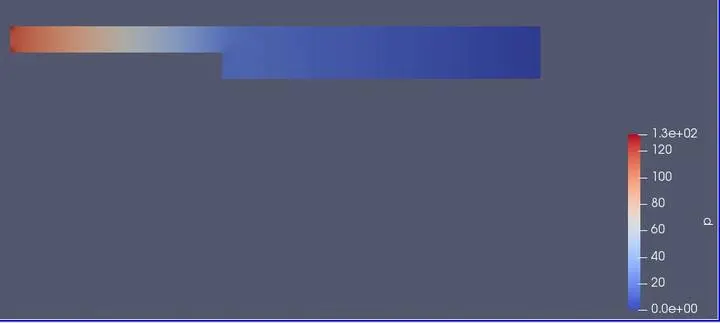
Pressure effect
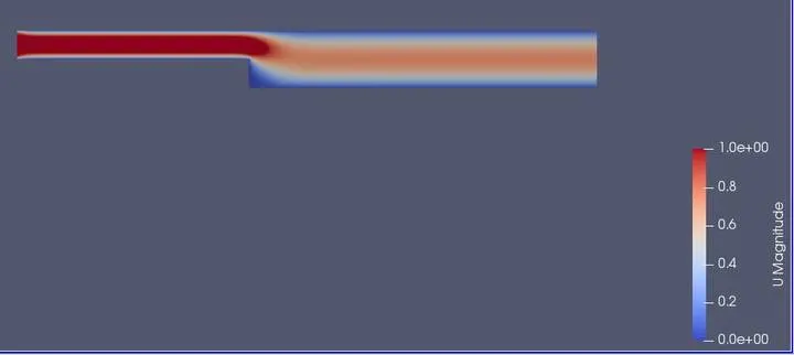
Velocity effect
Graph
case 2
Mesh

Pressure effect
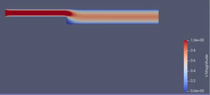
Velocity effect
Graph
case 3
Mesh

Pressure effect
Velocity effect
Graph
case 4
Mesh

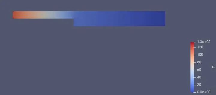
Pressure effect
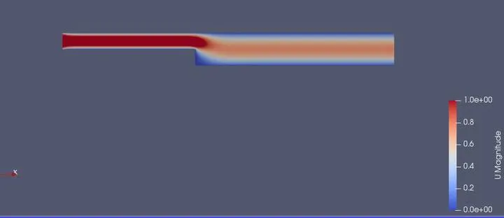
Velocity effect
Graph
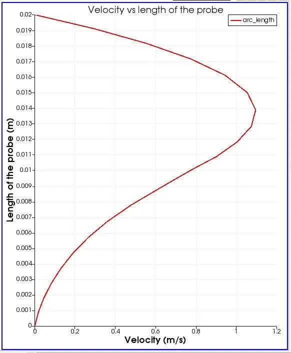
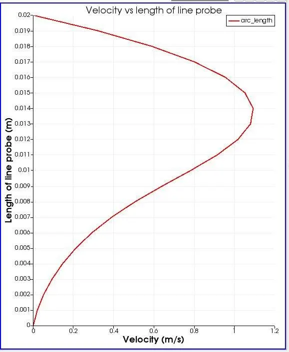
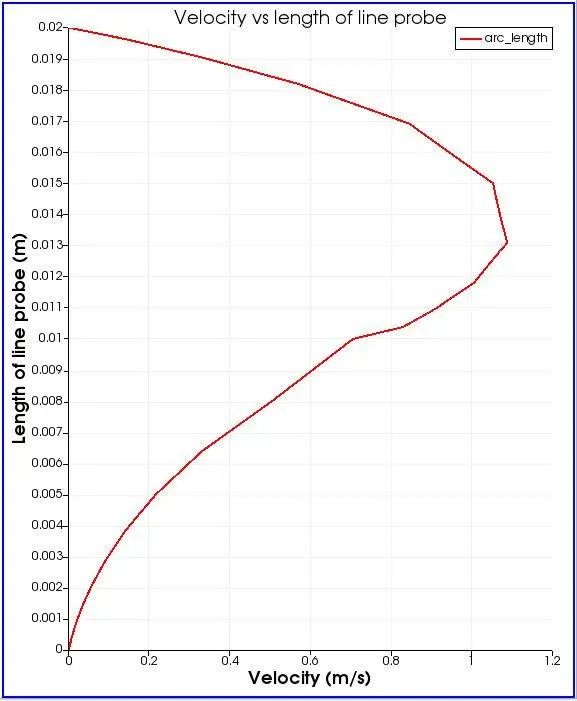
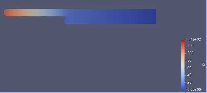
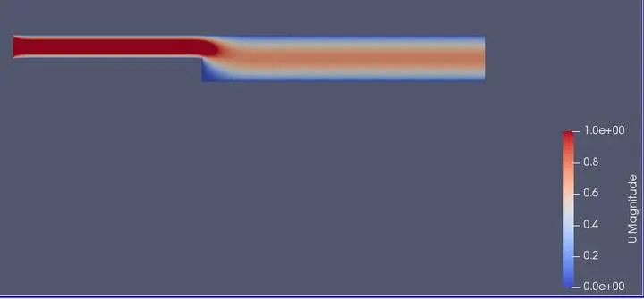
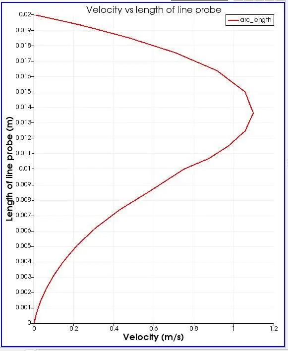
From the above graph, we can see that the graphs are almost the same we can see the difference when we zoom into the plot. They are giving almost the same answer. To get a more accurate answer we need to give the grading factor to be small. If we give the small value of the grading factor we will get the more accurate value.
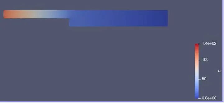
The maximum velocity value is between 0.013 to 0.014. It should be at mid-point. That's not happening because of the pressure developed by the internal force.
With the decreased value of the grading factor, our solution goes to the near the accurate value and it takes less time for the simulation.