BlockMesh Drill down Project
AIM:
The aim of this project is to simulate an incompressible-laminar-viscous flow through the backward-facing step geometry for a transient condition. While changing the grading factor.
PROCEDURE:
-
The given condition is an incompressible-laminar-viscous flow so we use the icoFoam solver to solve the problem.
-
Since we don't intend to build the problem from the scratch we will use a tutorial case for this.
-
We navigate to the tutorials folder using the “tut” command. In the tutorials folder, we have some example problems. We navigate to the incompressible folder (cd incompressible).
-
In the incompressible folder, we go to the icoFoam/cavity/cavity folder(cd cavity). Here we can find three types of files 0, constant, system.
-
Since we can't simulate in the original directory we copy this cavity folder to somewhere else.
-
In the new location which in my case is the run folder. We open the cavity folder in the run.
-
In the cavity folder, we have three other folders. 0 which is the initial conditions file, Constants which holds the values of all the constants involved in the process, System which holds all the information regarding the geometry, simulation setup, schemes to be used, etc.
-
This cavity folder is actually a simple scenario. It has a geometry that is being kept in a fluid flow. We need to understand what is happening to the velocity at a distance of 0.085m from the origin.
-
The parameters to be used for our simulation are as follows.
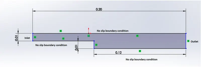
Number of cells along the X direction = 200
Number of cells along the Y direction = 20
-
To set up the given geometry we need to go to the system folder. Here we need to edit the blockMeshDict file.
-
This can be edited using any text editor. Like notepad, mousepad gedit preferably code editors like atom, VSC as they can detect machine languages.
-
In the vertices tab. We have some vertices we need to replace with new vertices.
-
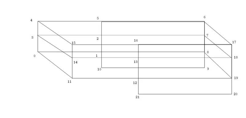
To find out the vertices of our geometry lets us first divide our geometry into blocks as shown

-
so for each block, we need to assign vertices if we start with 1st block we start with the bottom left point as the origin (0 0 0) and we go to the bottom right as 1
-
Then move to upright 2 and then top left 3, move on to 2nd block top right 4 and up left 5.
-
The complete picture would look like this
-
We enter all these vertices in the space given below the vertices tab in the blockMeshDict file. Note that the vertices defined have numbers allotted starting from 0 to end.
-
Since we’ve specified all the vertices we need to specify the blocks created.
-
Note that we need to define the block numbers in a counter-clockwise direction.
-
Just before the blocks is the type of mesh to be used which is hexagonal in our case. And after the blocks are defined we need to define the number of cells required for each block in x, y, and z directions respectively.
-
To get a uniform mesh size we need to keep in mind that the size of the mesh is the ratio of block length/No of cells.
-
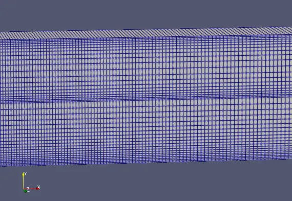
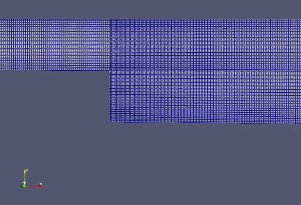
The next space provided after the cells block is for Mesh grading. Mesh grading is used to stretch the mesh in a particular direction. Say we know the values of certain parameters on one end and need to calculate the values of the same on the end. For better accuracy, we can keep the mesh size more on one side and less on the other size.
-
Since the mesh size is less there will more grid points on that side. This helps us achieve better accuracy on the unknown side.
-
In the space provided for grading, we need to provide grading factors for x y and z directions respectively. Grading factor is a quantity defined as
`text{grading factor} = text{size of the end cell} / text{size of the starting cell}`
-
For our project, we are going to vary the grading factor (1, 0.2, 0.4,0.8) and see how it affects the solution.
-
Before we proceed to simulation let us have a look at the controldict file which holds the values for the time.
-
We need to make sure that the courant number criteria is satisfied in my case I gave the dt as 1e-5. But a time step difference of this small will take more time on my machine. Hence I reduced the end time step to 0.01
-
Now we get back to the cavity folder. In a terminal, we type the following commands.
$ blockMesh - This command checks the geometry given and generates the mesh.
$ checkMesh - This command is optional not needed in most cases. This command ensures that the mesh is all good for the simulation.
$ icoFoam - This command tells OpenFOAM to solve the problem using the icoFoam solver.
$ paraFoam – This command opens the results in ParaView.
If everything were in place the files would look like this
blockMeshDict
/*--------------------------------*- C++ -*----------------------------------*
  =========                 |
  \      /  F ield         | OpenFOAM: The Open Source CFD Toolbox
   \    /   O peration     | Website:  https://openfoam.org
    \  /    A nd           | Version:  8
     \/     M anipulation  |
*---------------------------------------------------------------------------*/
FoamFile
{
    version     2.0;
    format      ascii;
    class       dictionary;
    object      blockMeshDict;
}
// * * * * * * * * * * * * * * * * * * * * * * * * * * * * * * * * * * * * * //

convertToMeters 0.01;

vertices
(
    (0 0 0)//0
    (8 0 0)//1
    (8 0.5 0)//2
    (0 0.5 0)//3
    (0 1 0)//4
    (8 1 0)//5
    (20 1 0)//6
    (20 0.5 0)//7
    (20 0 0)//8
    (20 -1 0)//9
    (8 -1 0)//10
    (0 0 1)//11
    (8 0 1)//12
    (8 0.5 1)//13
    (0 0.5 1)//14
    (0 1 1)//15
    (8 1 1)//16
    (20 1 1)//17
    (20 0.5 1)//18
    (20 0 1)//19
    (20 -1 1)//20
    (8 -1 1)//21
);

blocks
(
    hex (0 1 2 3 11 12 13 14) (200 10  1) simpleGrading (1 1 1)

    hex (3 2 5 4 14 13 16 15) (200 10 1) simpleGrading (1 1 1)

    hex (2 7 6 5 13 18 17 16) (300 10 1) simpleGrading (1 1 1)

    hex (1 8 7 2 12 19 18 13) (300 10 1) simpleGrading (1 1 1)

    hex (10 9 8 1 21 20 19 12) (300 20 1) simpleGrading (1 1 1)
);

edges
(
);

boundary
(
    inlet
    {
        type patch;
        faces
        (
            (0 11 14 3)
            (3 14 15 4)
        );
    }
    outlet
    {
        type patch;
        faces
        (
            (9 8 19 20)
            (8 7 18 19)
            (7 6 17 18)
        );
    }
    frontAndBack
    {
        type empty;
        faces
        (
            //Front
            (11 12 13 14)
            (14 13 16 15)
            (13 18 17 16)
            (12 19 18 13)
            (21 20 19 12)
            //Back
            (0 3 2 1)
            (3 4 5 2)
            (2 5 6 7)
            (1 2 7 8)
            (10 1 8 9)
        );
    }
    noslipwalls
    {
        type wall;
        faces
        (
            //Top
            (15 16 5 4)
            (16 17 6 5)
            //Bottom
            (11 12 1 0)
            (21 20 9 10)
            //Side step
            (10 21 12 1)

        );
    }
);

mergePatchPairs
(
);

// ************************************************************************* //
controlDict
/*--------------------------------*- C++ -*----------------------------------*
  =========                 |
  \      /  F ield         | OpenFOAM: The Open Source CFD Toolbox
   \    /   O peration     | Website:  https://openfoam.org
    \  /    A nd           | Version:  8
     \/     M anipulation  |
*---------------------------------------------------------------------------*/
FoamFile
{
    version     2.0;
    format      ascii;
    class       dictionary;
    location    "system";
    object      controlDict;
}
// * * * * * * * * * * * * * * * * * * * * * * * * * * * * * * * * * * * * * //

application     icoFoam;

startFrom       startTime;

startTime       0;

stopAt          endTime;

endTime         0.01;

deltaT          1e-5;

writeControl    timeStep;

writeInterval   20;

purgeWrite      0;

writeFormat     ascii;

writePrecision  6;

writeCompression off;

timeFormat      general;

timePrecision   6;

runTimeModifiable true;


// ************************************************************************* //
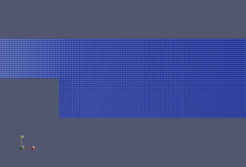
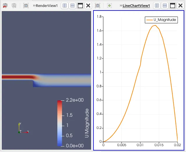
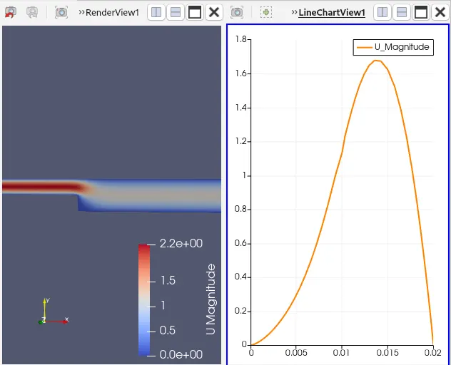
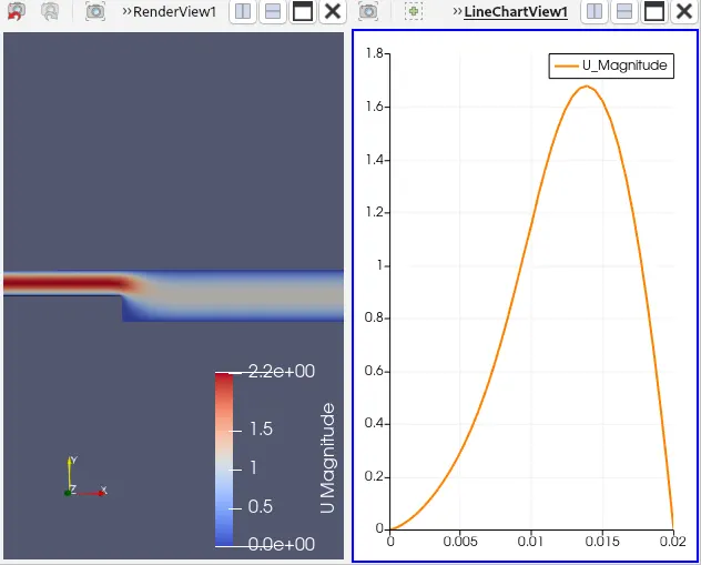
And we would get the following results. We get these graphs by using the plot over line option in the data analysis bar in the filters tab above in the menu.
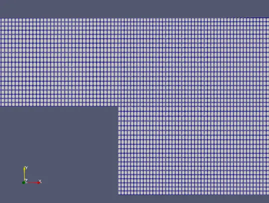
Grading factor 1
mesh
Velocity Profile
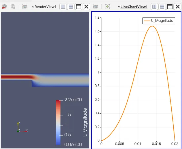
Grading factor 0.2
mesh
Velocity Profile
Grading factor 0.4
mesh
Velocity Profile
Grading factor 0.8
Mesh
Velocity Profile
CONCLUSION:
From the above graphs, we can see that the velocity profile is the same overall grading factors. Though mesh grading is good for simulations. The current problem we are dealing with has less effect on the change in grading factor.