Week 8-3D Tetra Meshing Challenge
AIM – To do Tetra Mesh on the given components.
OBJECTIVE
- To create Tetra Mesh for the housing component using method 2D to 3D conversion. With following Quality Criteria - Target element size -5, Minimum Element Length – 2, Maximum Element Length – 7 & Tet collapse – 0.15.
- For Model – 2 – To create 3D Tetra Mesh using volume Tetra method. With following Quality Criteria - Target element size -3 & Tet collapse – 0.15.
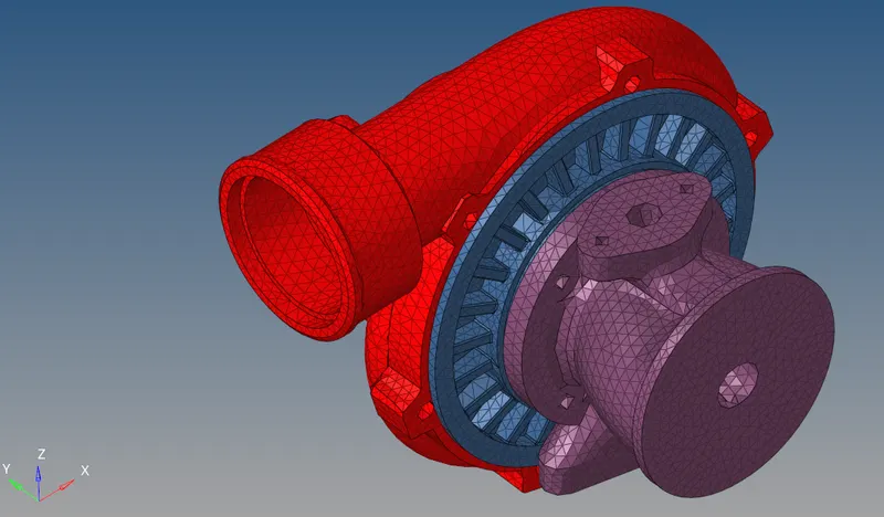
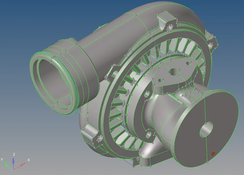
- To do 3D Tetra Mesh on Turbocharger using volume Tetra method. With following Quality Criteria - Target element size -4 & Tet collapse – 0.15.
CAD MODEL IMAGES:
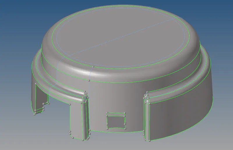
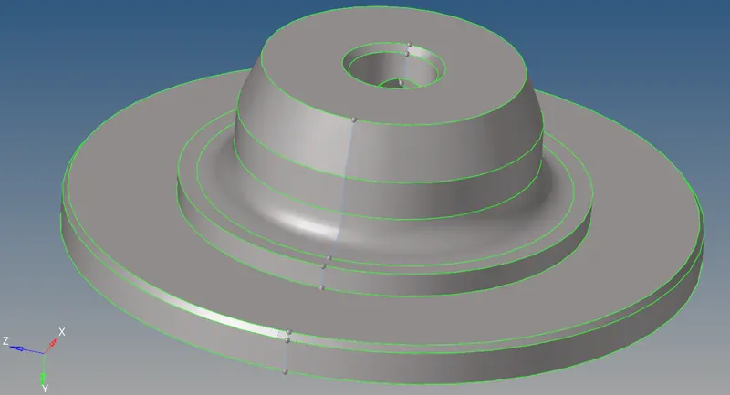
MODEL – 1:
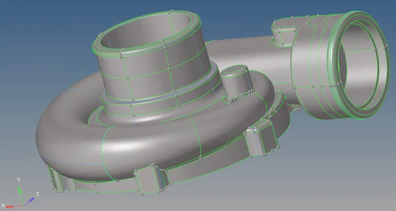
MODEL – 2:
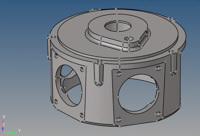
MODEL – 3:
PROCEDURE:
PROCEDURE Model – 1:
- At first Import the model then switch to Topology mode.
- There are two components, one is Hub and the other is casing. 2D meshing with Tria Elements were done on both casing by following the asked quality criteria.
- Before 2D meshing topology clean up was done on casing to avoid minimum element length failure. Other unnecessary lines were also toggled using geom → quick edit → toggle line. It can be seen in the above CAD image and below given image.
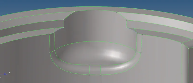
- Then Criteria file setting was done for 2D meshing Preferences → Criteria file setting. Then 2D meshing was done with Tria elements with element size 5 units. After meshing Element were fixed using F10 shortcut for checking element quality on minimum element and maximum element length and it was fixed before proceeding with 3D Tetra Mesh.
- After that 3D Tetra Meshing was done using command 3d → Tetra mesh → select the 2D elements → click mesh. Tetra mesh is complete.

- Tetra mesh was checked for Tet collapse and there were 0.0 % element failure.
PROCEDURE MODEL – 2:
- For model -2 few steps were same as above like importing and checking the geometry. The different steps followed for volume Tetra Mesh is given below.
- 3d → Tetra Mesh → Volume Tetra → select the solids → click mesh. Before meshing Target element size 4 was defined as shown in below and Tetra Mesh parameter option was checked to put Tet collapse value 0.15.

- Then elements were check for quality on parameter Tet collapse by pressing F10. 0.0 % elements were failing.
PROCEDURE MODEL – 3:
- At first the model was imported. It has 4 components. 1) Casing, 2) Hub, 3) Supporting Plate, 4) Holder Housing.
- The solid were deleted for each component Except Holder Housing. To get the surface.
- For each of the component Topology cleanup like Toggling few lines were done to avoid element size failure and unnecessary lines were also toggled. For Casing and Supporting plate I faced issues while doing Volume Tetra mesh. The issues were resolved by toggling lines using quick edit, changing the Tet form in quick Tetra option from floating to fixed and trimming surface using surface edit → Trim self-intersecting surfaces. Few duplicate surfaces were creating issues it was also resolved before volume tetra mesh.

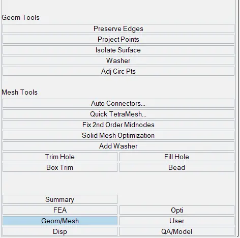
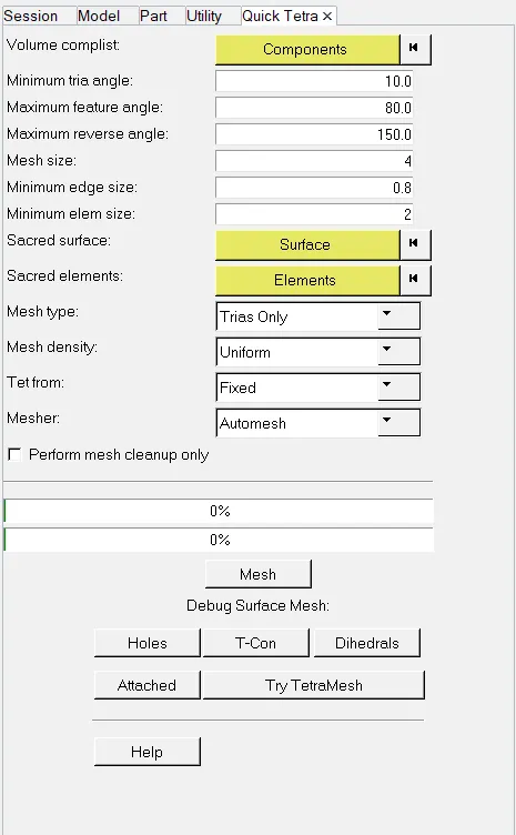
- Then Volume tetra meshing was done for Casing and Supporting plate using command View → Hypermesh → Utility → Geom/Mesh → Quick Tetra Mesh. Below is the image shown for the same. In quick Tetra Mesh setting Mesh size was change, minimum element length as provided, Mesh Type – Trias Only and Tet form – Fixed. Then the desired Volume Tetra Mesh was achieved. After checking for quality in Tet collapse there was 0.0% element collapsing. Same process was followed for Hub.
- After that Holder Housing were meshed using 3d → Tetra Mesh → Volume Tetra → select the solids → click mesh. After checking for quality in Tet collapse there was 0.0% element collapsing.
- In this the whole Turbo charger was meshed using 3D tetra mesh.
RESULTS:
- All the models were meshed in 3D Tetra Mesh.
- Two methods were followed to do 3D Tetra Mesh. 1) Converting the 2D elements to 3D and other was directly doing volume Tetra Mesh.
- All the models were cleared for Tet collapse.
FINAL MODEL IMAGES:
MODEL -1:
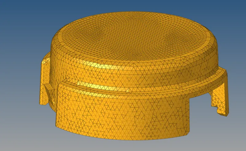
CASING:
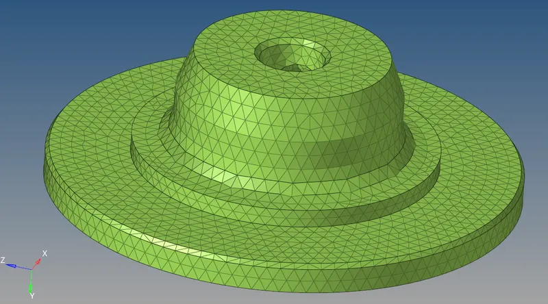
HUB:
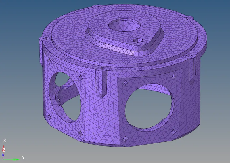
MODEL -2:
MODEL -3:
TURBOCHARGER: