Week - 4
AIM:
To implement control logic of a washing machine using Stateflow as per given sequence
- If the power supply is available the system gets activated.
- If the Water supply is not available then stop the process and indicate through LED.
- Soaking time should be 200s followed by Washing time of 100s.
- Then rinsing happens for next 20s and dryer runs for 50s.
THEORY
What is washing machine:
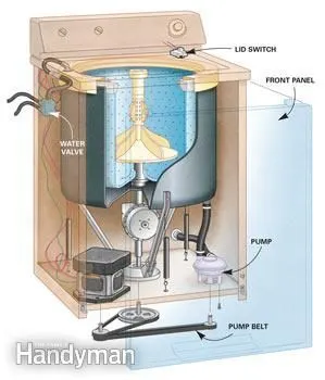
Washing machine is the machine that is used to wash the various types of clothes without applying any physical efforts. With washing machine you don’t have to rub the clothes with hand or squeeze them to remove the water from them. The washing machine is also called as clothes washer. The washing machine enables you to wash your clothes automatically without having to supervise its operation. All you have to do is put the clothes in the machine and select the wash mode. The washing machine automatically takes in the amount of water and detergent required and it also automatically sets the timer for washing, rinsing and drying as per the selected mode and the amount of clothes. A washing machine washes dirty clothes inside a barrel in which the clothes are placed. The barrel is filled with water and rotated along with clothes and detergents for washing.
TYPES OF WASHING MACHINE
Depending on the position of the barrel or loading the clothes there are 2 types of washing machine.
- Top load washing machine.
- Front loading washing machine.
Depending upon the mode of operations. Generraly top load washing machines are classified like this.
- Fully automatic washing machine.
- Semi automatic washing machine.
TOP LOAD WASHING MACHINE:
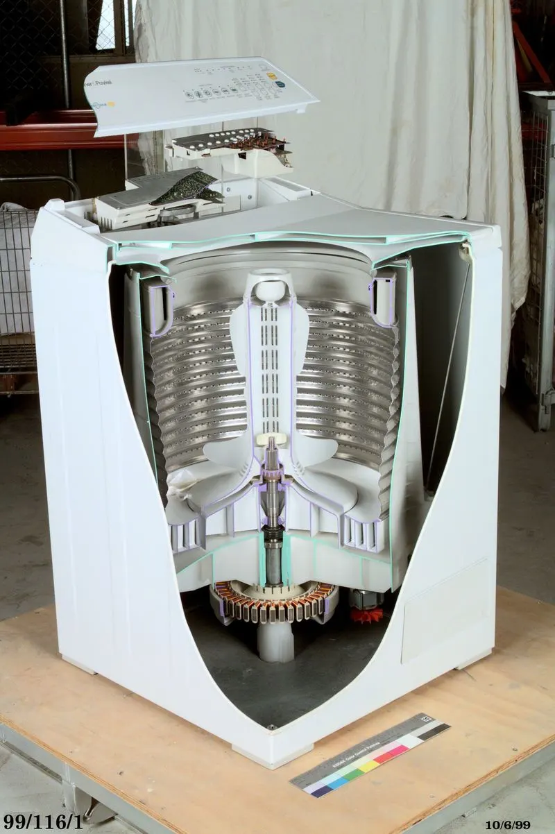
In this washing machine the clothes are loaded from the top of the washing machine. There is a cover at the top that helps loading and unloading of clothes in the round vessel that perform the function of the washer as well as the rinser and drier in the fully automatic washing machine.
FRONT LOAD WASHING MACHINE:
In this machine the clothes are loaded from the front side. The studies have shown that the front loading washing machines consume less electric energy, water and detergent and also give better washing results compared to the top loading washing machine.
FULLY AUTOMATIC WASHING MACHINE:
In fully automatic washing machine there is only one tub that serves as the washer, rinser as well as the drier. Depending on the number of clothes or the weight of the clothes the machine takes in the sufficient amount of water and detergent automatically and sets the timer for wash and drying automatically. All you have to do is just provide the water connection put the detergent from time-to-time in its storage space and put the clothes. The fully automatic washing machine does the rest of things automatically.
SEMI AUTOMATIC WASHING MACHINE:
This has separate tubs or vessels for the washer and the drier. There are two separate timers that enable setting washing and drying times. To wash the clothes you have to put the clothes in the wash vessel, put sufficient quantity of the water and detergent and then set the timer. After the specified time, the washing machine will stop. You can remove the clothes and dry them in the sun or you can dry them partially in the drier vessel by setting suitable time.
THE CONTROL LOGIC OF WASHING MACHINE USING STATEFLOW:
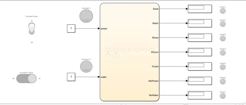
Below is the image of the model made in Simulink Stateflowfor control logic of washing machine.
- The image shown below shows the controll logic in no run condition when the power supply and water connection is in off mode. The process is not running.
- The below image shows the state flow logic applied inside the chart.
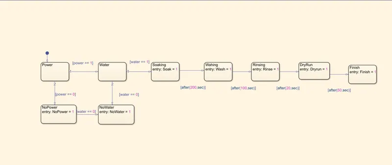
EXPLAINATION OF THE ABOVE IMAGE
- First the power state is defined if power == 1 then it will go to water state else power == 0 it will go to NoPower state where NoPower = 1 is the entry and when power is not availabel it will display 1 and the lamp will show green else yellow and from there if water == 0 the signal will go to NoWater state state where the entry is NoWater = 1 and when no water is available it will display 1 else 0 and the lamp will show blue color for no water else red.
- If water == 1 then the signal will go pass on to next state that is soaking and it will continue for 200 seconds afer it completion display block will show 1 and lamp will reflect green colour.
- After soaking the process will go to next state that is washing only after 200 seconds of soaking and same as above after it completion display block will show 1 and lamp will reflect green colour. It will continue for 100 seconds.
- After 100 seconds washing is completed and the process will move to next state Rinsing it will continue for 20 seconds and afer it completion display block will show 1 and lamp will reflect green colour.
- After Rinsing that 20 seconds the process will move to DryRun state which will continue till 50 seconds and afer it completion display block will show 1 and lamp will reflect green colour.
- After 50 seconds of DryRun the process will move to next state that is finish, the display block will show 1 and lamp will reflect green color and the washing of clothes is over.
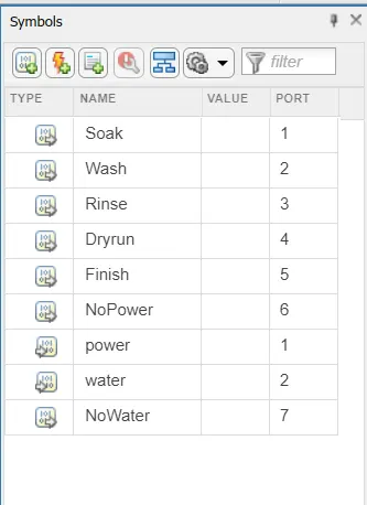
- The below image shows the Symbols pane where the input and outputs are defined.
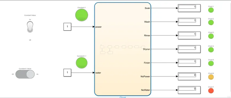
- The below image shows the required results when the power supply and water supply are switched on.
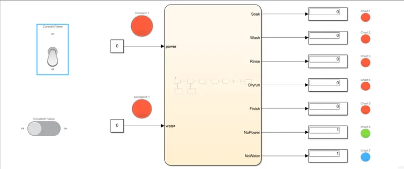
- The below image shows the result when no power supply is available and no water supply due to which the process stops and all the process are indicated by red color lamp. When no water is there the lamp indicates blue and for no power the lamp indicates green.
- The below image shows the result when only power supply is avilable and no water supply due to which the process stops and washing does not happen. The same are indicated by lamps. The 0 in display block shows that the process has not yet started.
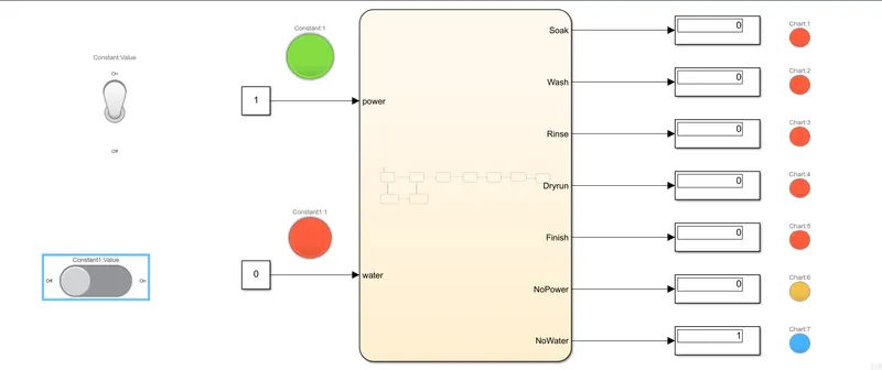
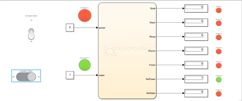
- The image below shows the result when only water supply is available but no power supply as without power the motor cannot run so the process has stopped and same is reflected by the red colour indicating lamps. No power supply gives signal 1 to display block to show that there is no power and the noWater signals 0 in the display block showing the water is available with red color lamp.
Ans 2 ) Simulink chart for the Gear shift logic as per below conditions. Input for speed will be provided while the simulation is running and gear shift will be observe in the display block.
Speed Range(kmph) Gear
0 to 15 1
16 to 25 2
26 to 40 3
41 to 60 4
Above 61 5
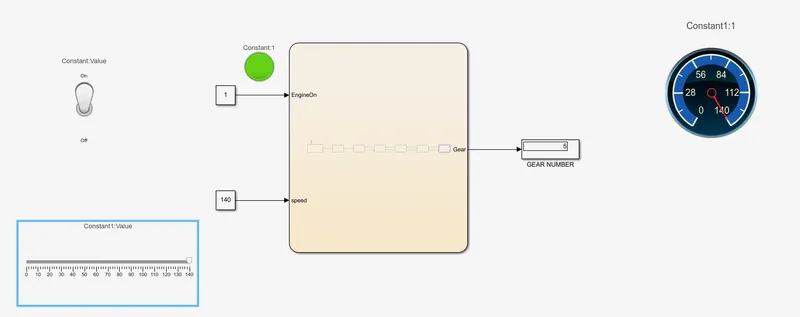
Below are the images of simulink model along with chart which is use to showcase the above logic along with there results.
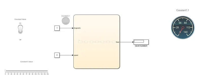
- The simulink chart in no run condition. The run button is not yet pressed. The run time or stop tme is infinity - inf.
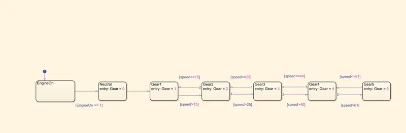
- The simulink chart containing logic.
EXPLAINATION OF THE ABOVE LOGIC
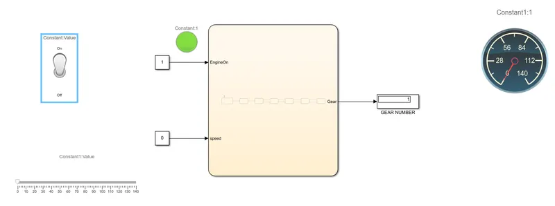
- First the Engine is turned ON by toggle switch which is indicated by green lamp, if the engine is ON the state directly jumps to gear 1 state according to the given speed conditon that is speed<=15 and the gear display automatically shows 1 and while giving speed input by slider which is displayed by custom guage if the speed is less than or equal to 15 then the gear position will be 1 and the state will remain in Gear 1.
- When the speed is greater than 15 the state will go to Gear 2 state and stay there till speed is less than equal to 25. Speed is given by slider which is displayed by custom guage which acts as speedometer. The gear position 2 will be displayed by gear display block.
- When the speed is greater than 25 the state will go to Gear 3 state and stay there till speed is less than equal to 40. Speed is given by slider which is displayed by custom guage which acts as speedometer. The gear position 3 will be displayed by gear display block.
- When the speed is greater than 40 the state will go to Gear 4 state and stay there till speed is less than equal to 61. Speed is given by slider which is displayed by custom guage which acts as speedometer. The gear position 4 will be displayed by gear display block.
- When the speed is greater than 61 the state will go to Gear 5 state and stay there until the speed falls back to 61. Speed is given by slider which is displayed by custom guage which acts as speedometer. The gear position 5 will be displayed by gear display block.
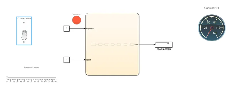
- The below image shows when the Engine is Off. Which is indicated by red color lamp. So the gear displayed is Zero.
- The below image shows when the Engine is ON and it is indicated by green lamp and gear displayed is 1 cause speed is less than 15 Km/hr.
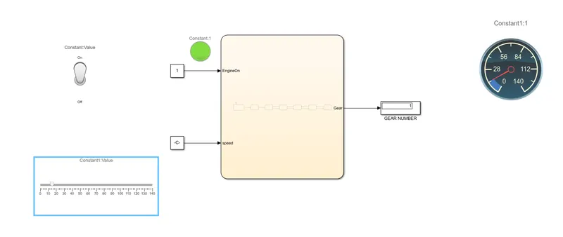
- Postion Gear 1 displayed in Gear Number display block and the speed is just below 15 which can be observe from the sllider.
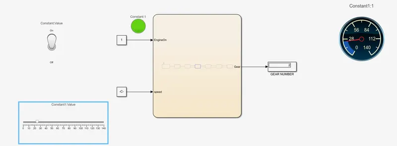
- Postion Gear 2 displayed in Gear Number display block and the speed is just below 25 which can be observe from the sllider.
- Postion Gear 3 displayed in Gear Number display block and the speed is just below 40 which can be observe from the sllider.
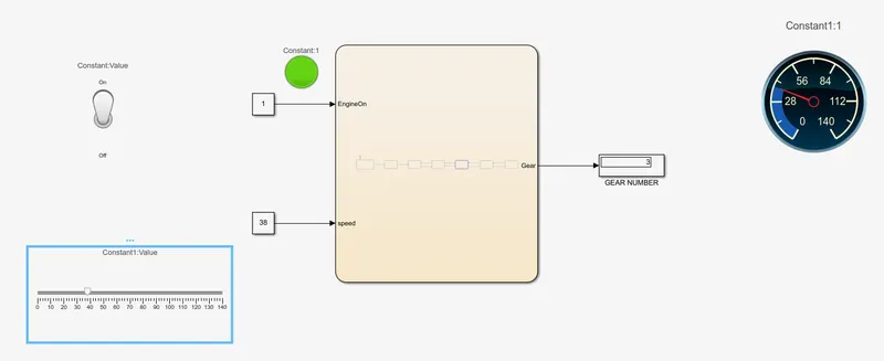
- Postion Gear 4 displayed in Gear Number display block and the speed is just below 61 which can be observe from the sllider.
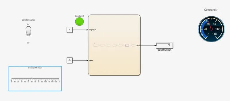
- Postion Gear 5 displayed in Gear Number display block and the speed is just above 61 which can be observe from the sllider.According to condition given gear 5 should be shifted above 61 which is full filled.
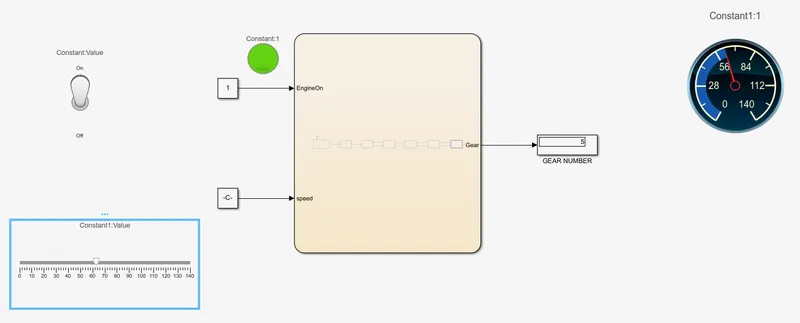
- Postion Gear 5 displayed in Gear Number display block at full speed that is 140 which can be observe from the sllider.