Week 8-3D Tetra Meshing Challenge
AIM:- To study 3D Tetra Meshing Challenge with the help of HYPERMESH.
OBJECTIVES:-
1. Creating a Teramesh for Housing component with the following quality criteria.
TetraMesh Generation Method: 2D to 3D Conversion Elements sizes: Min- 2 Units, Target- 5 Units, Max- 7 Units .Tet collapse: 0.15
2. For the given model, Create a 3D Tetramesh with the following quality criteria by quick tetramesh or volume tetra mesh method TetraMesh Generation Method: Quick Tetra Mesh/ Volume Tetra Mesh Target Element size: 3 Units. Tet Collapse: 0.15
3. For the given assembly model, Create a 3D Tetramesh with the following quality criteria. TetraMesh Generation Method: Quick Tetra Mesh/ Volume Tetra Mesh Target Element size: 4 Units. Tet C/ollapse: 0.15
Q.1. Create a Teramesh for Housing component with the following quality criteria.
TetraMesh Generation Method: 2D to 3D Conversion
Elements sizes: Min- 2 Units, Target- 5 Units, Max- 7 Units
Tet collapse: 0.15
Ans:-
1. Importing the Geometry
To import geometry to the hypermesh first we need to switch the solver on which we are going to work here especially working on radios. after changing the solver we will see the components file to check the file format in which they saved here in the given assignments the component files are saved in .hm format and to import them simply we can do to file menu and by clicking on open option we can see the model by clicking on model option hypermesh will take us to the browse directory to entering in the desired file we can see our working file by clicking on open option hypermesh do all the process of generating and reading of the file and withing time the component will visible on the screen.
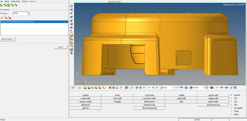
FILE>IMPORT>GEOMRETRY>SELECT(selecting desired file>IMPORT>
2. Deleting solids
for that we will go to DELETE pannel and delete solid from component
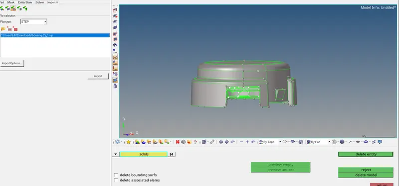
GEOMETRY>SOLIDS(selecting solids as per we want to delete solids)>DELETE ENTITIES.
3. GEOMETRICAL FIXING
Fixing some geometrical features for better mesh flow, mostly in the areas where the higher possibilities of minimum size element error. so we are toggling them.
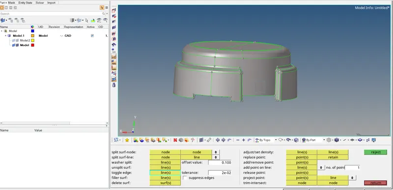
GEOMTERY>QUICK EDIT>TOGGLE EDGE>LINE>TOOGLE.
after fixing the geometry will go for meshing.
4. MESHING THE COMPONENT
We will first use model no 1 from the given project.
so, in this case, we are going to convert 2D TO 3D mesh. so first we will be going to mesh this component by using a 2D mesh with a trias element of size 5 and as it is we using surface mesh so elements are going to save in the 2D surface component.
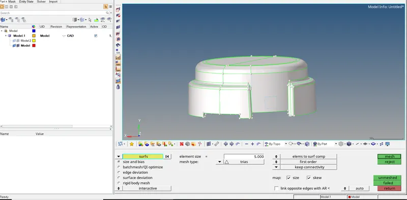
2D>SURF(selecting the displayed option so the whole component is going to be highlighted)>ELEMENT SIZE (5)>ELEMENT TYPE(trias)>MESH.
Also, we are using the smooth option for better mesh flow.
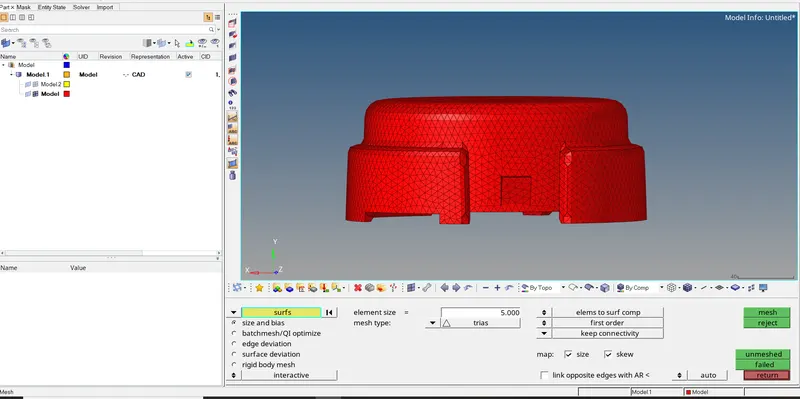
as we meshed our given component we will go for quality criteria for fixing minimum size errors and maximum size errors.
for that, we will go to the TOOL menu and in which check element.
Min- 2 Units, Target- 5 Units, Max- 7 Units
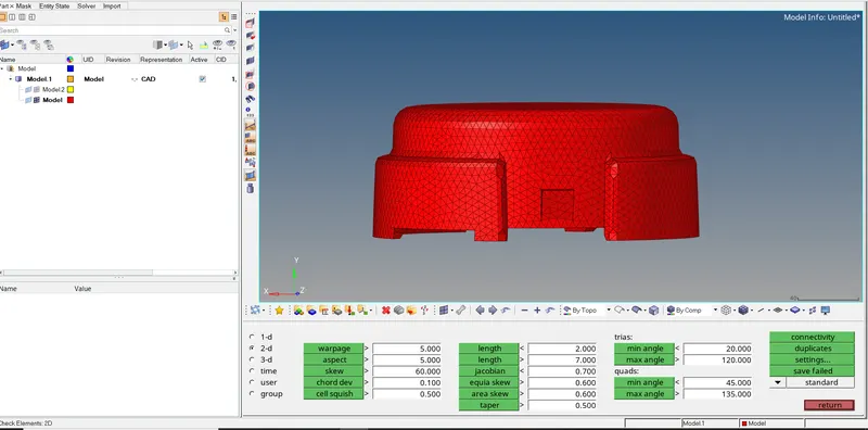
first, we will check the minimum length our given minimum element size is 2 so element sizing below 2 units will be failed
5. MINIMUM LENGTH ELEMENT
after clicking on the minimum element fail element. we can see the highlighted elements which are actually failed elements.
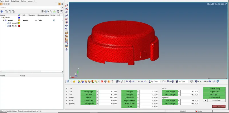
1. as we can see there are 20 elements failing for minimum length so to fix that first we need to sort them from all the elements so we will use the save failed option.
2 after that we will go to the mask tool in which element option exists under element option we will use the retrieved option which will retrieve the failed elements which we save and then we will hit the mask option so the failed elements will be masked and after clicking on the reverse option the screen will only show failed elements
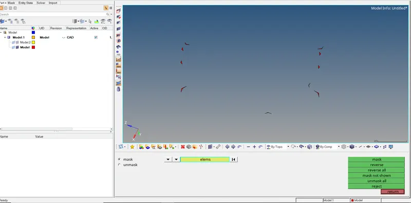
MASKK>ELEMENTS>RETRIVE>MASK>REVERSE
as we can only see failed elements we will try to fix them by moving the nodes so elements failing for minimum length manually.
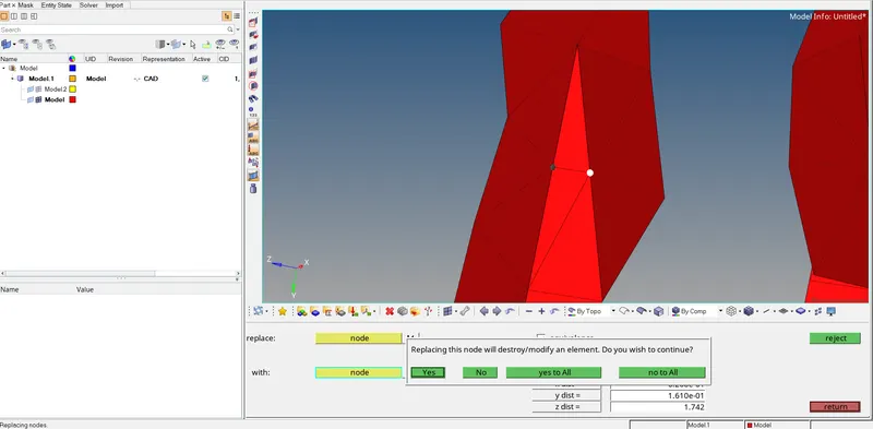
for that, we will use replace option under 3D pannel.
3D>REPLACE>NODE(Replace the node with the desired node >OK
and that will fix the failure of the element for minimum length, one by one we will fix all the elements.
and to bring back all the elements we will simply use unmask all options.
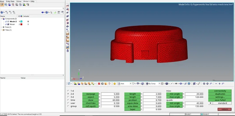
we can see now there is no element failing for minimum length and the minimum length maintained is 2.03
6. MAXIMUM LENGTH ELEMENT
For eliminating failed element for maximum length we need to remesh the element by selecting its surrounding element
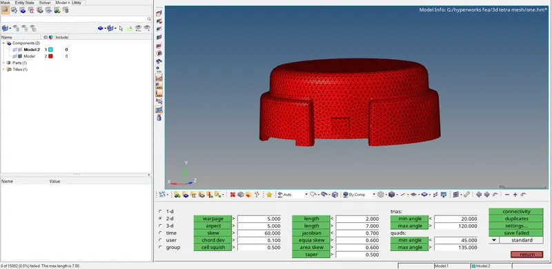
we can zero element failing for maximum length and the maximum length maintain is 7.00
7.3D TETRAMESHING
after creating the 2d mesh we will move to the tetra mesh panel which is under the 3d panel so here we are going to create a tetra mesh but before that, we need to set some parameters that we can set under the tetra mesh parameters in which we will focus on element quality target and under that we will set tetra collapse value as 0.17 which is greater than the given value so whatever element failing for tetra collapse will restrict to 0.17 so there will be no element failing for tetra collapse and it will make our meshing and quality report easy otherwise we need to fix that element one by one and it will take more time after setting parametric value we will move to tetra mesh.
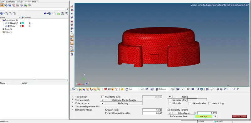
so in tetra mesh and we will select as a component in determining condition for tetra element creation by keeping other parameters and setting as it is
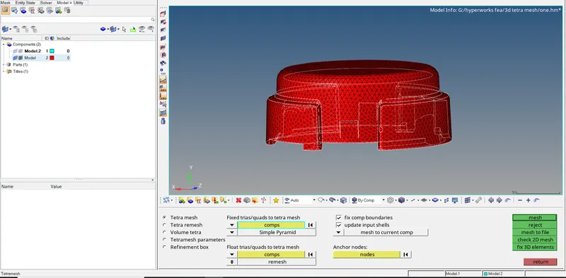
and after hitting on mesh button we will get our desired mesh we can see that in the image below
if it's showing that your mesh is not enclosed we can look for free edges so we will move to edges under the tool manual and select the component and click on free edges and hypermesh will create a new component with free edges so we can directly delete them by delete edges option and then we go for tetramesh.
there will be a new component created in a model tree with tetramesh,
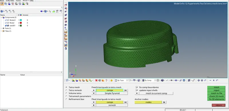
so in the above image we can see there are tetra mesh tasks are completed but those are not visible to us to check and confirm that it is actually happening so we will move to the mask panel where we can mask elements
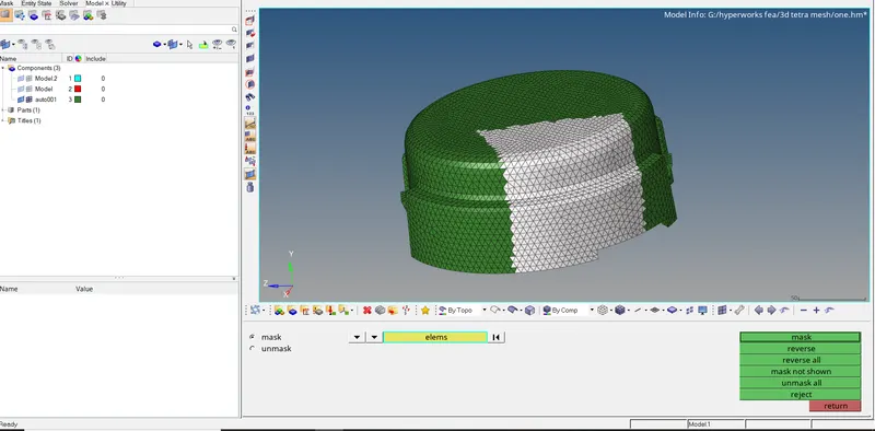
to see the structure so we are going to drag the mouse over some elements by clicking the left mouse button which we want to mask to see the inner structure and same time we will press the shift button and those elements turn into white color and by hitting the mask button they will hide we can see image below to observe them,
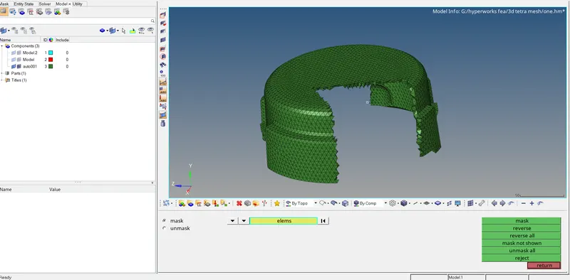
so we can see here there are tetra are created so our first task is completed after that we can simply unmask them all. now we need to check for quality criteria and in which our main concern is tetra collapse
8. QUALITY CRITERIA
to check this we will move under the tool panel in which check elements present in that as these are 3d elements we will move under 3d pannel and in which we click on tet collapse button after clicking on it will throw a message in left bottom of the window with how many elements failing for tetra collapse and also it shows the minimum tetra collapse value.
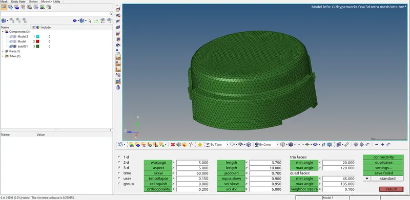
the image above shows there are zero elements failing for tetra collapse and the minimum tetra collapse value is 0.259950 which is greater than 0.15 which was our criteria value so we successfully created a 3d tetra mesh
after this, we will move to our next component which is a hub for that we will use different methods of 3d tetra mesh.
the second part of the housing component is a flange,
the procedure is almost simple so we will avoid the small steps to describe
and will directly jump into the meshing part.
1.2D MESHING:-
so there are few methods to create 3d mesh but here we are using the 2d to 3d mesh conversion method first we will create a 2d surface on convert with tria elements and element size 5 and remaining parameters as it is so we are not going to check for any quality criteria in 2d panel
after hitting on mesh button we can see trias are created on the surface in the image below,
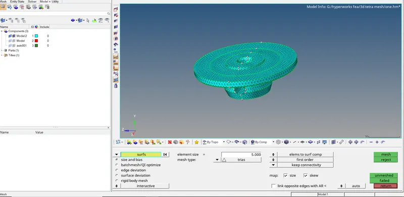
2D>SURF(selecting the displayed option so the whole component going to be highlighted)>ELEMENT SIZE (5)>ELEMENT TYPE(trias)>MESH.
Also, we are using the smooth option for better mesh flow.
2. MINIMUM LENGTH ELEMENT
after clicking on the minimum element fail element. we can see the highlighted elements which are actually failed elements.
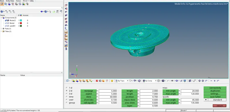
1. as we can see there is 1 element failing for a minimum length of 1.98 and our criteria is 2 units so to fix that first we need to sort them from all the elements so we will use the save failed option.
2 after that we will go to the mask tool in which element option has existed under element option we will use the retrieved option which will retrieve the failed elements which we save and then we will hit the mask option so the failed elements will be a mask and after clicking on the reverse option the screen will only show failed elements
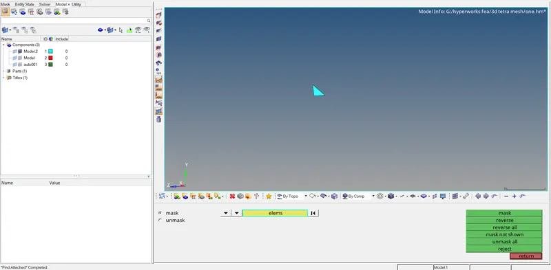
for that, we will use replace option under 3D pannel.
3D>REPLACE>NODE(Replace the node with the desired node >OK
and that will fix the failure of the element for minimum length, one by one we will fix all the elements.
and to bring back all the elements we will simply unmask all options.
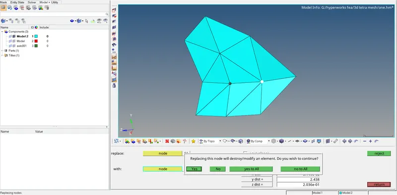
for that, we will use replace option under 3D pannel.
3D>REPLACE>NODE(Replace the node with the desired node >OK
and that will fix the failure of the element for minimum length, one by one we will fix all the elements.
and to bring back all the elements we will simply unmask all options.
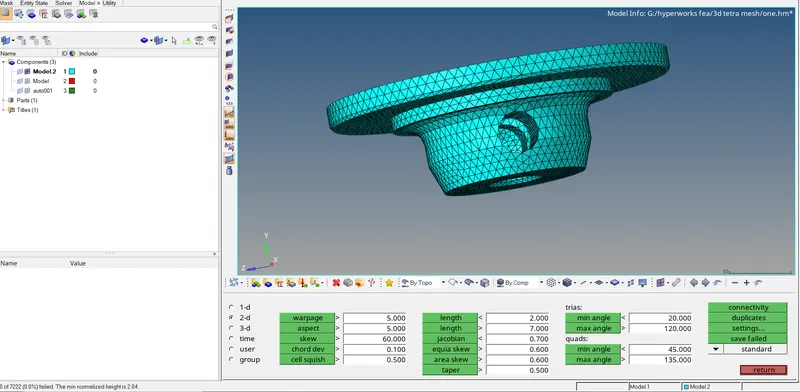
we can see now there is no element failing for minimum length and the minimum length maintained is 2.04
3. MAXIMUM LENGTH ELEMENT
For eliminating failed element for maximum length we need to remesh the element by selecting its surrounding element
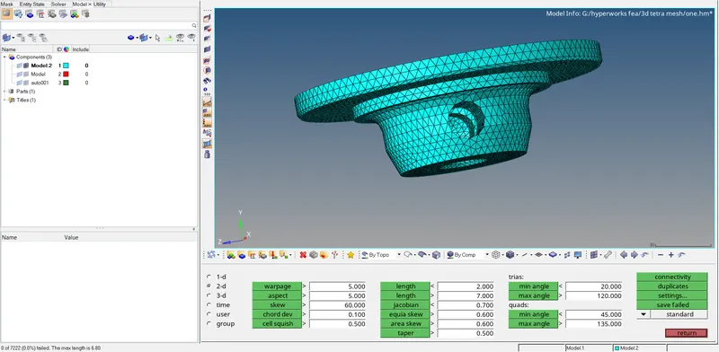
we can see now there is no element failing for maximum length and the minimum length maintained is 6.80
4.3D TETRAMESHING
after creating the 2d mesh we will move to the tetra mesh panel which is under the 3d panel so here we are going to create a tetra mesh but before that, we need to set some parameters that we can set under the tetra mesh parameters in which we will focus on element quality target and under that we will set tetra collapse value as 0.17 which is greater than the given value so whatever element failing for tetra collapse will restrict to 0.17 so there will be no element failing for tetra collapse and it will make our meshing and quality report easy otherwise we need to fix that element one by one and it will take more time after setting parametric value we will move to tetra mesh.
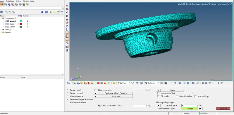
so in tetra mesh and we will select as a component in determining condition for tetra element creation by keeping other parameters and setting as it is,
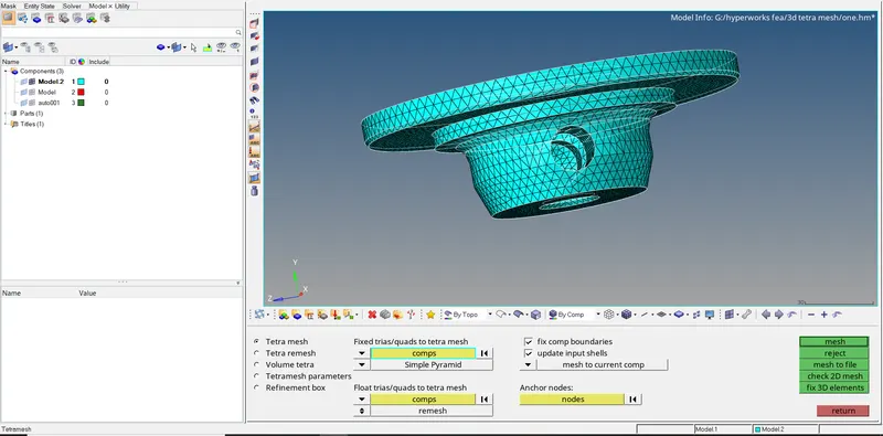
and after hitting on mesh button we will get our desired mesh we can see that in the image below,
(NOTE:-if it's showing that your mesh is not enclosed we can look for free edges so we will move to edges under the tool manual and select the component and click on free edges and hypermesh will create a new component with free edges so we can directly delete them by deleting edges option and then we go for tetramesh)
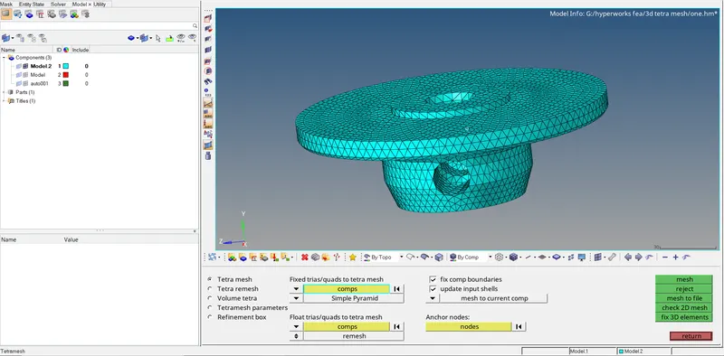
so in the above image we can see there are tetra mesh tasks completed but those are not visible to us to check and confirm that it is actually happening so we will move to the mask panel where we can mask elements.
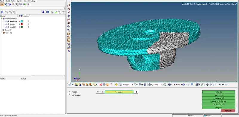
to see the structure so we are going to drag the mouse over some elements by clicking the left mouse button which we want to mask to see the inner structure and same time we will press the shift button and those elements turn into white color and by hitting the mask button they will hide we can see image below to observe them,
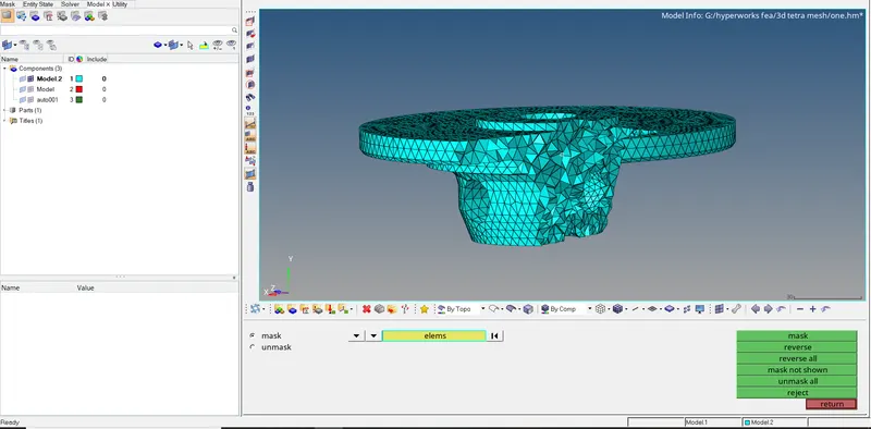
so we can see here there are tetra are created so our first task is completed after that we can simply unmask them all now we need to check for quality criteria and which our main concern is tetra collapse
5. QUALITY CRITERIA
to check this we will move under the tool panel in which check elements present in that as these are 3d elements we will move under 3d pannel and in which we click on tet collapse button after clicking on it will throw a message in left bottom of the window with how many elements failing for tetra collapse and also it shows the minimum tetra collapse value.
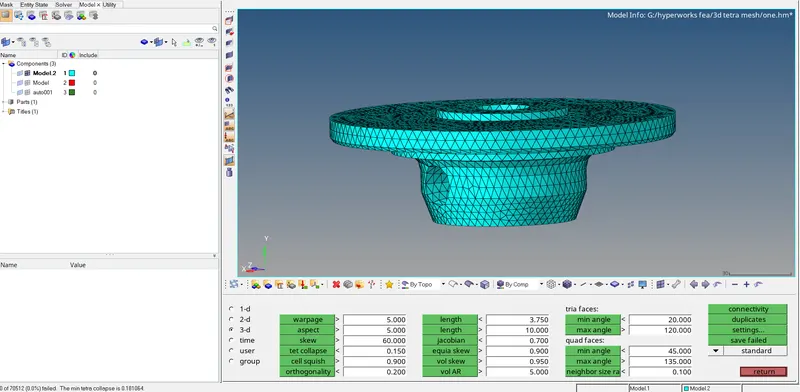
the image above shows there are zero elements failing for tetra collapse and the minimum tetra collapse value is 0.181064 which is greater than 0.15 which was our criteria value so we successfully created a 3d tetra mesh
**************************************************************************************************
2. For the given model, Create a 3D Tetramesh with the following quality criteria.
TetraMesh Generation Method: Quick Tetra Mesh/ Volume Tetra Mesh
Target Element size: 3 Units.
Tet Collapse: 0.15
1. IMPORTING COMPONENT TO HYPERMESH.
To import geometry to the hypermesh first we need to switch the solver on which we are going to work here especially working on radios. after changing the solver we will see the components file to check the file format in which they saved here in the given assignments the component files are saved in .iges format and to import them simply we can do to file menu and by clicking on Import and inside that we will select importin option as geometry so there will be new tab open in a model tree with import name and inside that we will get option such as FILE TYPE and we select IGES as our file type because our file saved in .iges format then browsing to file save location and selecting that file and clicking on import button file will appear on our screen
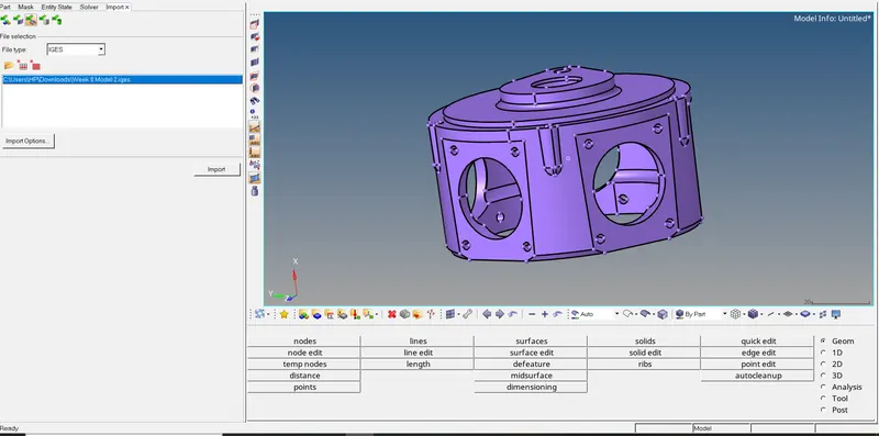
FILE>IMPORT>GEOMRETRY>FILE TYPE(.iges)>SELECT(selecting desired file>IMPORT
2. Deleting solids
for that, we will go to DELETE pannel and delete solid from component
3. QUICK TETRAMESH
so the quick tetramesh is as similar as surface mesh but the advantage is that it saves us time as the name suggest quick tetramesh it does all the procedure on its own Quick tetra mesh also works similarly to the above method. It first generates 2D surface elements and then converts them to generate the tetra mesh but is a much faster and more automatic method to generate tetra mesh. The drawback of this method is that the user has no control over the mesh quality.
Quick tetra mesh tool is accessed by going to View>Browsers>Hypermesh>Utility>Geom/Mesh>Quick tetramesh. In the Quick tetra mesh tool, the component & surfaces are selected, mesh size is set to 3mm, and mesh type is set to Trias only. After clicking on mesh, a new component is generated with the tetra mesh.,
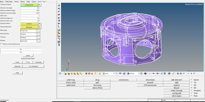
and by hitting on mesh button tetramesh will be created and also 3D tetramesh will be created with another component name.
once the process is done the message box will pop -up with the message the surface mesh is completed and attempted tetramesh once you hit ok for that message you can see the surface message is done and also tetramesh is done and inside new component.with the name Quick_tetras we can see the image below,
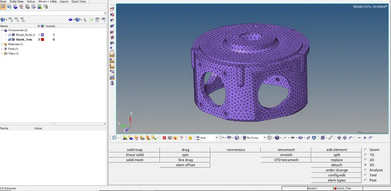
so in the above image we can see there are tetra mesh tasks completed but those are not visible to us to check and confirm that it is actually happening so we will move to the mask panel where we can mask elements.
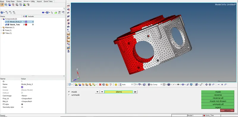
to see the structure so we are going to drag the mouse over some elements by clicking the left mouse button which we want to mask to see the inner structure and same time we will press the shift button and those elements turn into white color and by hitting the mask button they will hide we can see image below to observe them,
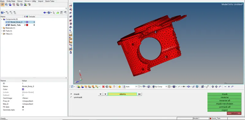
so we can see here there are tetra are created so our first task is completed we can simply unmask them all. now we need to check for quality criteria and in which our main concern is tetra collapse
4. QUALITY CRITERIA
as we saw the method we use is pretty quick but it compromise with quality so there will be many elements failing for tetra collapsed and fixing tetra collapse will be hectic for us and consume a large amount of time.so we simply fixed them with tetra remesh inside tetramesh panel we need to set some parameters that we can set under the tetra mesh parameters in which we will focus on element quality target and under that we will set the tetra collapse value as 0.17 which is greater than the given value so whatever element failing for tetra collapse will restrict to 0.17
to check this we will move under the tool panel in which check elements present in that as these are 3d elements we will move under 3d pannel and in which we click on tet collapse button after clicking on it will throw a message in left bottom of the window with how many elements failing for tetra collapse and also it shows the minimum tetra collapse value.
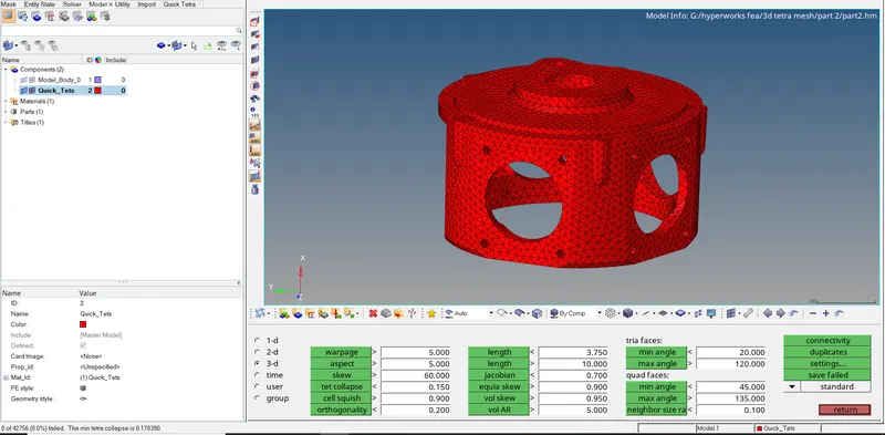
the image above shows there are zero elements failing for tetra collapse and the minimum tetra collapse value is 0.170390 which is greater than 0.15 which was our criteria value so we successfully created a 3d volume tetra mesh
******************************************************************************************
3. For the given assembly model, Create a 3D Tetramesh with the following quality criteria.
TetraMesh Generation Method: Quick Tetra Mesh/ Volume Tetra Mesh
Target Element size: 4 Units.
Tet Collapse: 0.15
1. IMPORTING COMPONENT TO HYPERMESH.
To import geometry to the hypermesh first we need to switch the solver on which we are going to work here especially working on radios. after changing the solver we will see the components file to check the file format in which they saved here in the given assignments the component files are saved in .hm format and to import them simply we can do to file menu and by clicking on open option we can see the model by clicking on model option hypermesh will take us to the browse directory to entering in the desired file we can see our working file by clicking on open option hypermesh do all the process of generating and reading of the file and withing time the component will visible on the screen.
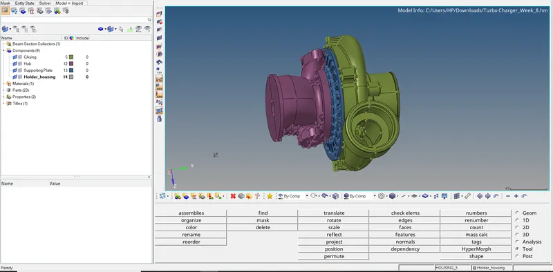
so our current model contains 4 components we going to mesh them one by one with volume tetramesh
1. Casing
2. Hub
3. Supporting plate
4. Holder housing
FILE>MODEL>OPEN>SELECT(selecting desired file>IMPORT
so for this question will be showing one component as an example because the procedure is the same out of the four components
2. VOLUME TETRAMESH
so as we are here dealing with tetramesh in the first part of the challenge we have done the normal tetramesh The volume tetra mesher works directly with surface or solid geometry to automatically generate a tetrahedral mesh without further interaction with you. Even with complex geometry, this method can often generate a high-quality tetra mesh quickly and easily.
this model already has elements created so we need to delete the previous elements so we can delete them by delete panel by selecting elements as a selection method
so here our given element size is 4 units and checking the proximity and curvature boxes check-in so the surfaces nearby holes and curve elements will have minimum length elements so they can capture the features perfectly
so for this question will be showing one component as an example because the procedure is the same out of the four components
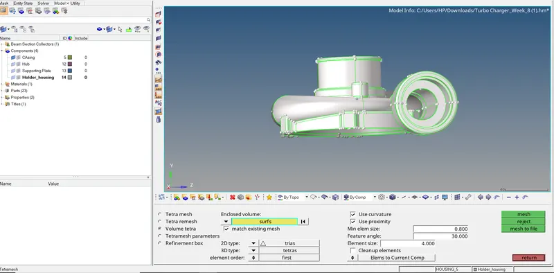
we need to set some parameters that we can set under the tetra mesh parameters in which we will focus on the element quality target and under that we will set the tetra collapse value as 0.17 which is greater than the given value so whatever element failing for tetra collapse will restrict to 0.17
the similar procedure we have done for all the components
so there will be no element failing for tetra collapse and it will make our meshing and quality report easy otherwise we need to fix that element one by one and it will take more time. after setting the parametric value we will move to volume tetramesh.
the image below we can see how tetramesh is generated
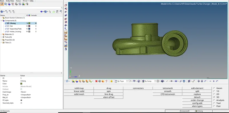
so in the above image we can see there are tetra mesh tasks completed but those are not visible to us to check and confirm that it is actually happening so we will move to the mask panel where we can mask elements.
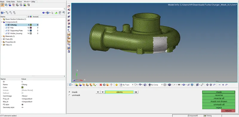
to see the structure so we are going to drag the mouse over some elements by clicking the left mouse button which we want to mask to see the inner structure and same time we will press the shift button and those elements turn into white color and by hitting the mask button they will hide we can see image below to observe them,
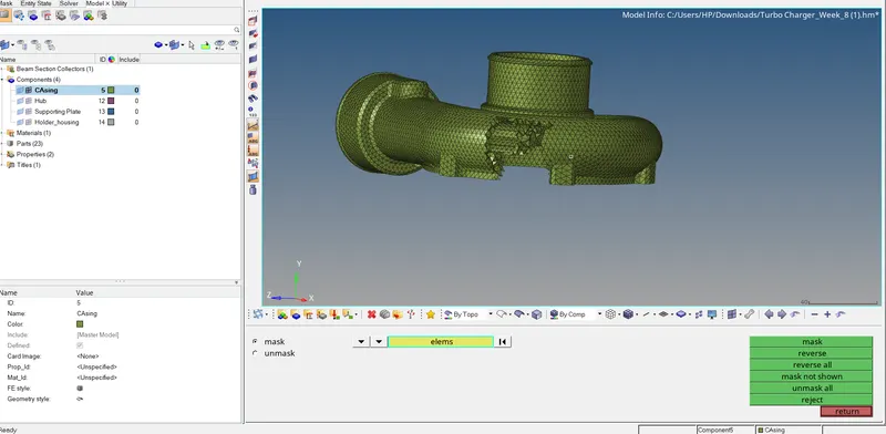
so we can see here there are tetra are created so our first task is completed we can simply unmask them all. now we need to check for quality criteria and which our main concern is tetra collapse
similarly same procedure for all the components.
3. QUALITY CRITERIA
to check this we will move under the tool panel in which check elements present in that as these are 3d elements we will move under 3d pannel and in which we click on tet collapse button after clicking on it will throw a message in left bottom of the window with how many elements failing for tetra collapse and also it shows the minimum tetra collapse value.
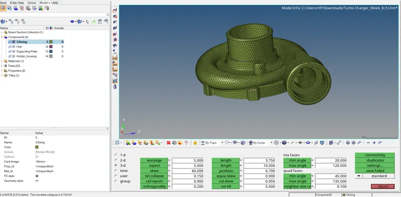
the image above shows there are zero elements failing for tetra collapse and the minimum tetra collapse value is 0.150167 which is greater than 0.15 which was our criteria value so we successfully created a 3d volume tetra mesh
similarly we check tet collapse for all the components and there were zero elements failing for tet collapse.
we can see the image below,
HUB:-
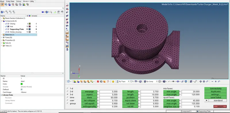
the image above shows there are zero elements failing for tetra collapse and the minimum tetra collapse value is 0.150118 which is more significant than 0.15 which was our criteria value so we successfully created a 3d volume tetra mesh.
SUPPORTING PLATE:-
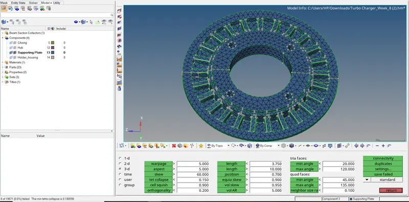
the image above shows there are zero elements failing for tetra collapse and the minimum tetra collapse value is 0.180598 which is more significant than 0.15 which was our criteria value so we successfully created a 3d volume tetra mesh.
HOLDER HOUSING:-
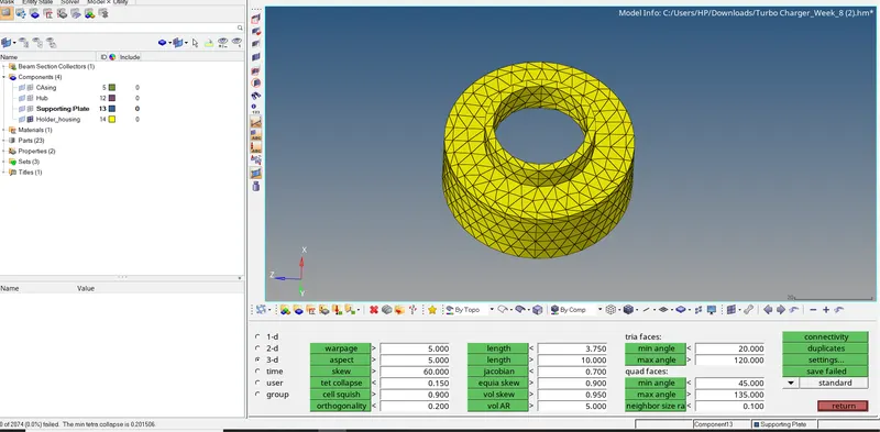
the image above shows there are zero elements failing for tetra collapse and the minimum tetra collapse value is 0.201506 which is more significant than 0.15 which was our criteria value so we successfully created a 3d volume tetra mesh.
RESULT:-
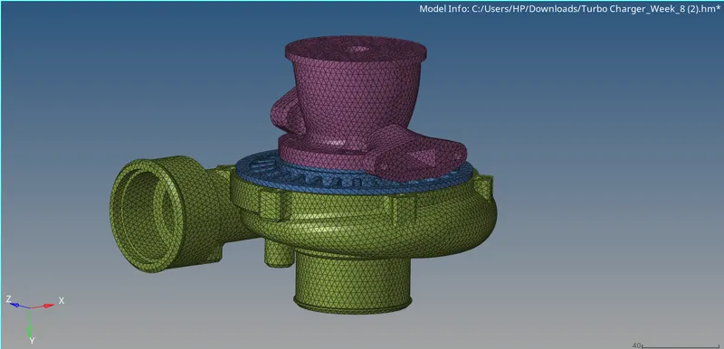
CONCLUSION:-
1. we learned different types of tetra meshing which are tetramesh. volume tetramesh, quick tetra meshing.
2. we learn how to resolve tetra collapse failure.
3. 2D to 3D Conversion of mesh.
(NOTE:- All the related data we attach below)