Week 8-3D Tetra Meshing Challenge
TETRA MESH.
AIM: 1) To deploy tetra mesh on housing model by crating 2d shell element and converting it into 3d elements.
2) To generate tetra mesh on model 2 and 3 component using volume tetra/ quick tetra option.
PROCEDURE:1) MODEL 1: BY CREATING 2D SHELL ELEMENT AND CONVERTING IT INTO 3D.
1)Open hyper works desktop student version 2021. Select the user interface as Opti struct and import given housing model.
IMPORT MODEL →IMPORT GEOMETRY→SELECT THE FILE TYPE AS IGES → SELECT THE LOCATION WHERE IT IS SAVED →IMPORT.
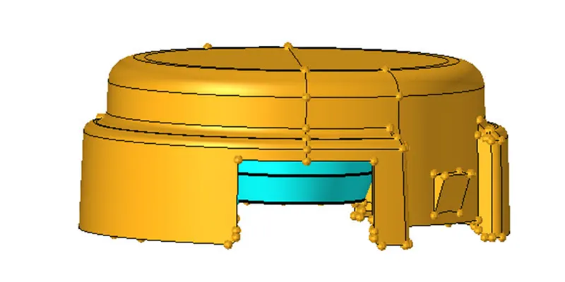
2) If we will see there is two parts, we model it separately.
3) We will perform geometry clean-up.
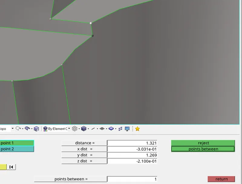
In the above image if we will see the part has region where the distance is less than minimum length so to avoid the failure of element, we will paste the node and make that surface flat.
To paste the point:
GEOM→QUICK EDIT (PRESS F11) →SELECT THE NODE TO BE REPLACED AND THE NODE TO BE RETAIN.
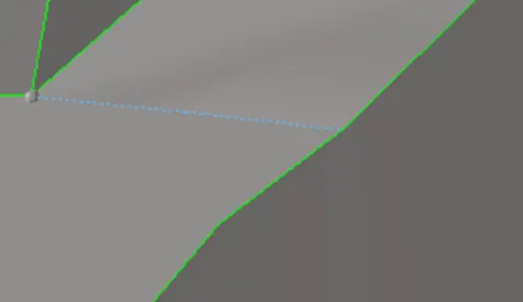
4) Defeature the fillets which is less than minimum length i.e., 2mm and toggle the feature line which is very close to each other.
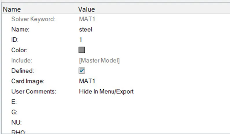
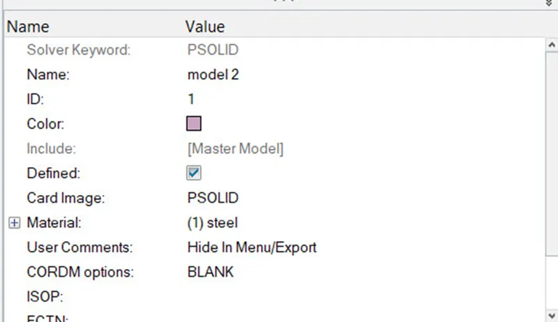
5)Now, create property card and material card. In property card select the card image as PSOLID instead PSHELL.
RIGHT CLICK→ CREATE→MATERIAL→SPECIFY NAME (STEEL).
RIGHT CLICK→CREATE→PROPERTY→ASSIGN THE MATERIAL → SELECT THE CARD IMAGE AS PSOLID→OK.
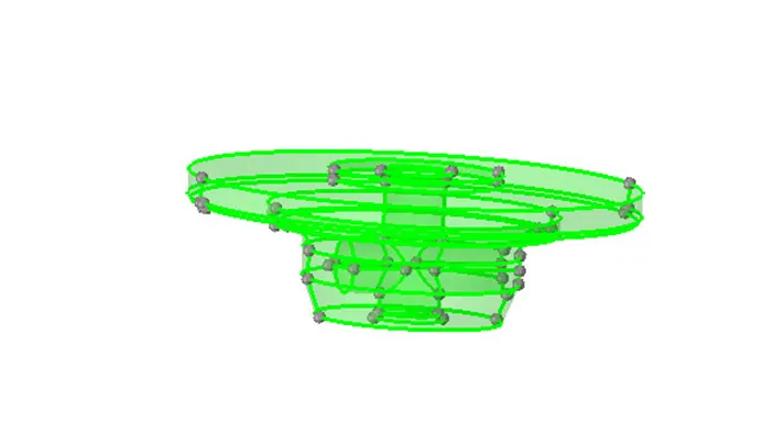
6)For generating mesh first delete the solids.
Delete the solids
DELETE→SOLIDS→SELECT THE SOLIDS → DELETE ENTITY.
7) Now we will generate mesh. While selecting element type instead of mixed we will select tria.
NOTE: Use R tria for curvy region and tria for flat regions.
2D→ AUTOMESH (F12) → SELECT ELEMENT TYPE AS TRIA → ENTER THE TARGET ELEMENT LENGTH → SELECT THE SURFACE → MESH.

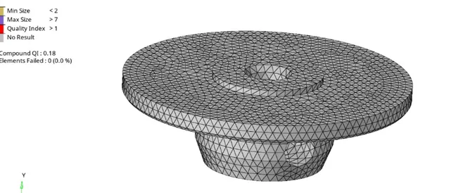
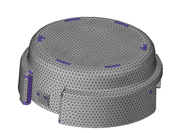
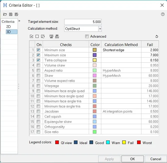
If we will see in the above image the elements are failing for min and max length criteria to fix this issue, we will use rebuild mesh option.
2D→REBUID MESH →EDIT THE MESH PARAMETER AND QUALITY CRITERIA → APPLY → OK.
Hence, 2d mesh is generated.
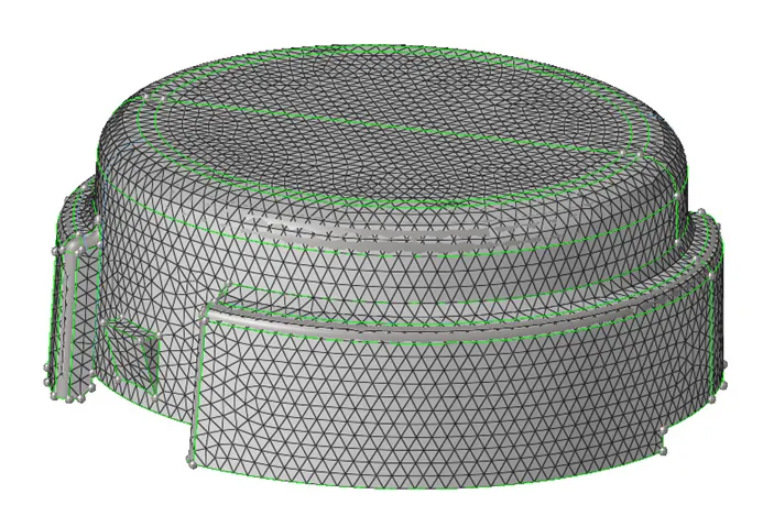
8) Now we will create 3d tetra elements from 2d elements using tetra mesh option from 3d panel.
3D→TETRA MESH→FIXED TRIA/QUADS TO TETRA MESH (ELEEMNTS)→SIMPLE PYRAMID→UNCHECK FIX COMP BOUNDARIES AND UPDATE INPUT SHELL BOX → MESH.

Now we will mask few elements and ensure whether tetra mesh is generated or not.
F5→ SELECT FEW ELEMENT→MASK.
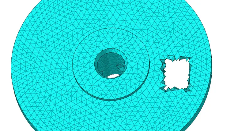
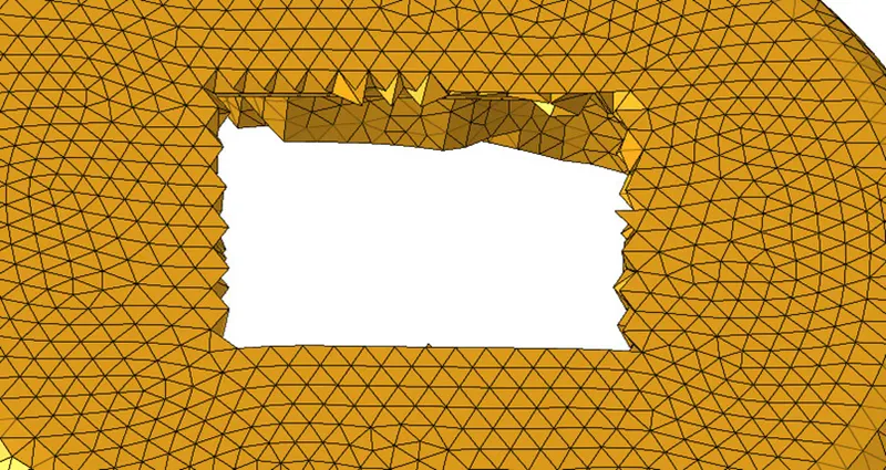
9) Now we will check elements failing for tet collapse (F10) and we will fix it if the elements are failing using tetra Re-mesh and by paste and distance option.

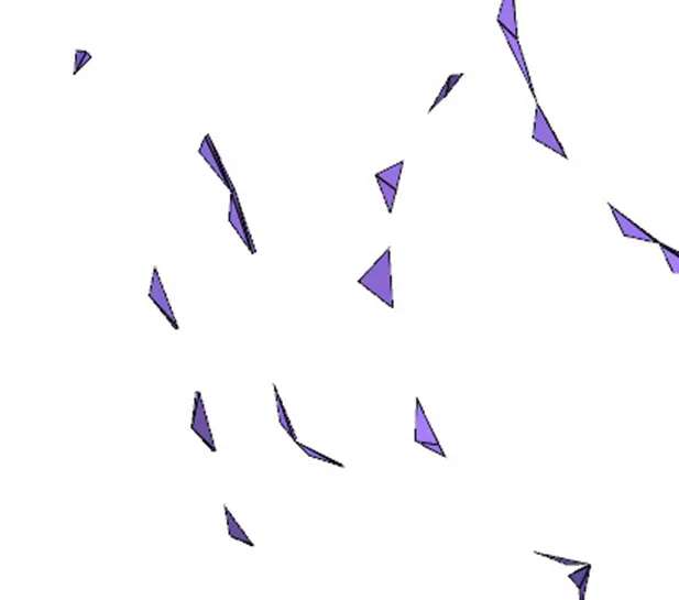
The above image depicts the element failing for tet collapse.
To fix elements failing for tet collapse follow the steps:
!) Unmask the adjacent element and try to fix it using tetra re mesh option.
3D→TETRA REMESH→ SELECT THE ELEMENTS→RE MESH.

Still the elements are failing for tet collapse use paste option and distance option to fix it.
For pasting:
F3→ PASTE→CHECK PASTE TO MIDPOINT AND EQUIVALANCE OPTION→ OK.
For using distance option:
F4 →GIVE THE DISTANCE BETWEEN TWO NODES→ OK.
Hence, 3d mesh is generated by creating 2d elements.
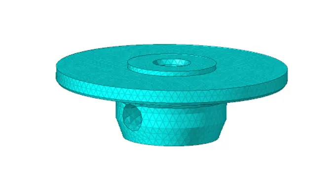
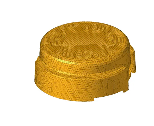
Now we will save the model.
FILE→SAVE AS→MODEL→ SPECIFY THE NAME AND LOCATION → SAVE.
2) MODEL 2: GENERATION OF TETRA MESH USING VOLUME TETRA/ QUICK TETRA OPTION.
1) Open the given CAD model in hyper works desktop student version 2021 and import the model.
IMPORT MODEL →IMPORT GEOMETRY→SELECT THE FILE TYPE AS IGES → SELECT THE LOCATION WHERE IT IS SAVED →IMPORT.
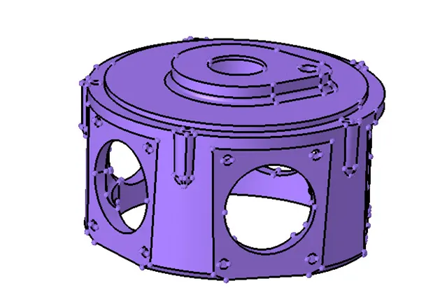
2) For this model we will create tetra mesh by solid selection. So, we will not delete the solid.
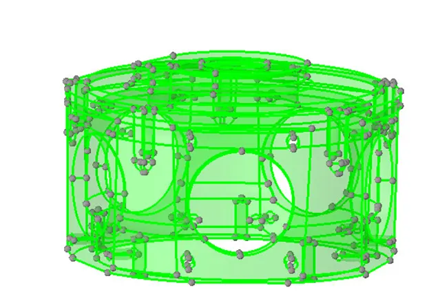
3) Make sure the model is a closed volume. There is no gaps or duplicate if there is any missing or duplicate surface resolve that issue
4)To generate mesh using volume tetra option.
3D→TETRA MESH → VOLUME TETRA MESH → SOLIDS→ ENTER ELEMENT SIZE→ UNCHECK USE CURVATURE AND PROXIMITY OPTION→ ELEMENT ORDER AS FIRST ORDER → MESH.
Reason for unchecking the use curvature and proximity option is if, we will enable that option there will be detailed feature capturing and number of nodes and elements will increase also the elements failing for tet collapse also increase this is the reason why we uncheck both the option.

Now to check whether mesh is generated or not we will mask few elements.
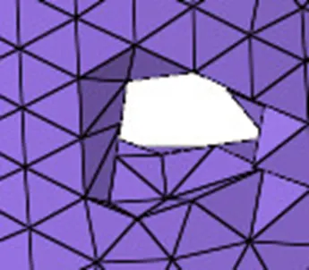
Now check whether the elements are failing for tet collapse if, it is failing use similar approach as we did for housing model.
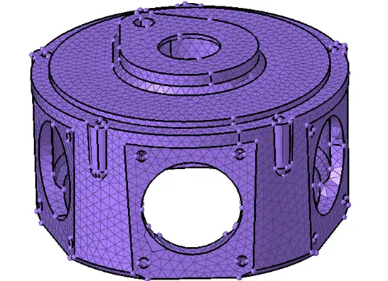
Hence, mesh is generated using volume tetra option. Now save the model.
FILE→SAVE AS→MODEL→ SPECIFY THE NAME AND LOCATION → SAVE.
3) MODEL 3: DEPLOYING MESH USING VOLUME TETRA/ QUICK MESH OPTION:
1) Open the given CAD model in hyper works student version 2021. Select the interface as Opti struct and import the model.
IMPORT MODEL →IMPORT GEOMETRY→SELECT THE FILE TYPE AS IGES → SELECT THE LOCATION WHERE IT IS SAVED →IMPORT.
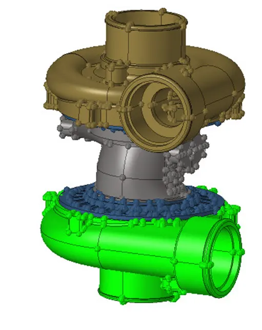
2) Now we will generate mesh separately in each component either by selecting solid or by surfaces.
3) Similar procedure needs to be followed which we did for model 2
4) For this model as well, we will uncheck the curvature and proximity option only the changes we will make is the element size value and the selection (solid/ surface).


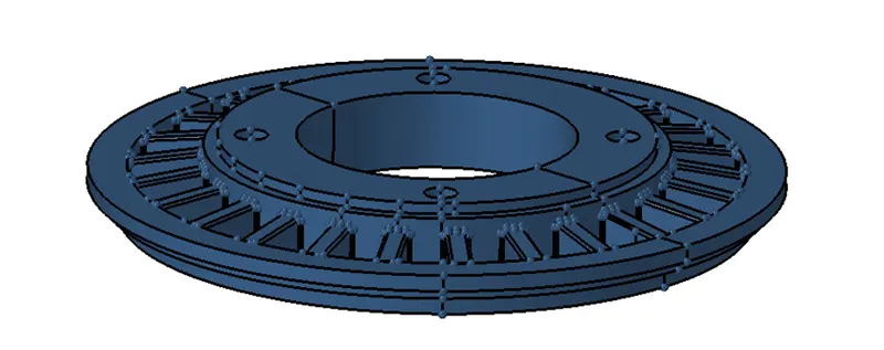
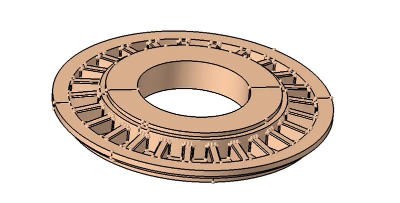
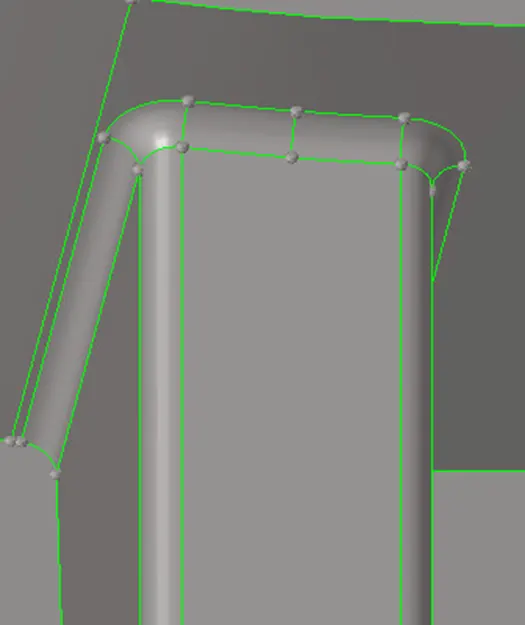
Now if we will see in the above images the parts have rib. The fillet radius of the rib is very less which leads to tet collapse element failure.
In order, to save the element from failing for tet collapse we will defeature it.
To defeature:
GEOM→ DEFEATURE→ SURF FILLETS→SELECT THE SURFS→ ENETER THE MAX AND MIN RADIUS → FIND→REMOVE.
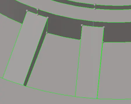
The above image shows the ribs after defeaturing.
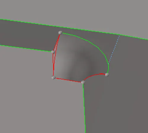
If we will see in the above image some portion of the fillet is not properly defeatured. Delete that surface and try to create a surface using ruled and extent option.
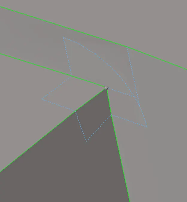
The above image depicts the surface generated after deleted the improper surface.
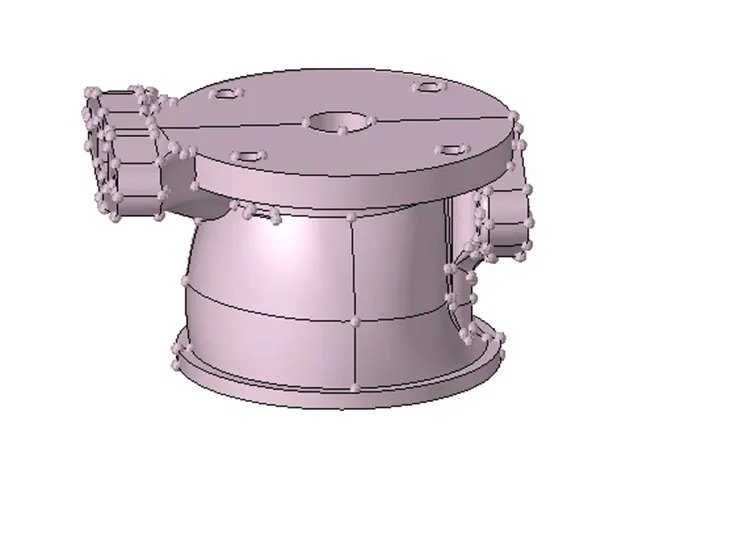
For the above part there is surface which is penetrating on each other.
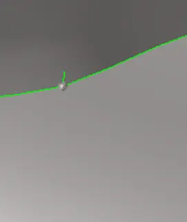
Resolve this by creating and delete and creating new surfaces in order to generate tetra mesh without any problem.
Rest of the procedure will remain same as we did in model.
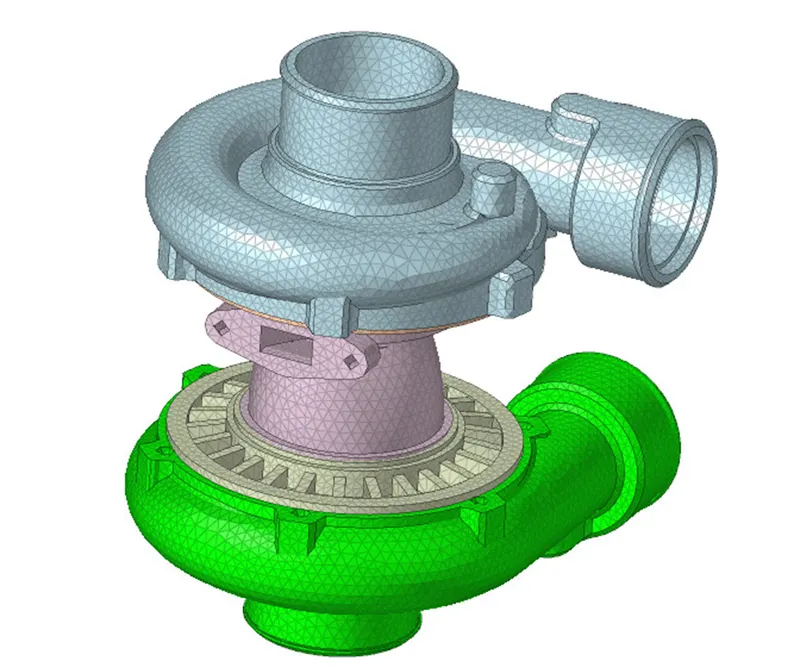
Hence, tetra mesh is deployed on model 3 using volume tetra option. Now save the model.
NOTE: We generally use first approach that is creation of 2d elements and then converting it to 3d.
Volume tetra option is used when we are not much concern with quality of the elements.
Both the approach is useful as per their requirement. We can opt first approach if we want better quality of mesh element and we can use volume tetra option when we want to generate rough mesh.
LEARNING OUTCOMES: 1) To deploy tetra mesh by creating 2d shell elements and converting it into 3d tetra elements.
2) To generate tetra mesh using volume tetra option.
3) When to use curvature and proximity option.
4) To check how many elements are failing for tet collapse.
5) To fix the elements failing for tet collapse using distance, paste and tetra re mesh option.
CONCLUSION: Hence tetra mesh is generated on all the three model by using both the approach.