Week 3 - 2D meshing for sheet metal
CAR HOOD MODEL.
AIM: To do geometry cleanup and to generate mid-surface, meshing on car hood model.
PROCEDURE: 1) Open CAD model in ANSA.
FILE→OPEN→LOCATION→ENTER
2) Check for the geometry. If there are any errors. Resolve those errors.
TOOLS→CHECKS→GEOMETRY→EXECUTE.
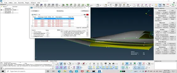
3) First try to fix these errors by auto fix. If the errors are not resolved by auto fix then use different modules in topo mod to resolve these errors.
4) Once errors are resolved again verify the geometry.
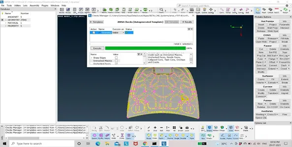
5) Create mid-surface for different parts in car hood model manually.
TOPO→FACES→OFFSET→SELECT THE FACE ON WHICH MIDSURFACE IS TO BE CREATED→CONFIRM (MIDDLE MOUSE) →SPECIFY DISTANCE→DELETE ORIGINAL FACE (YES/NO).
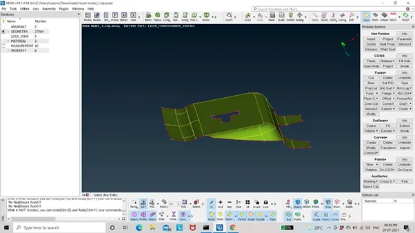
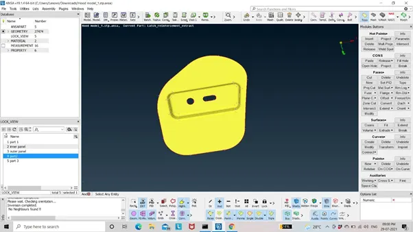
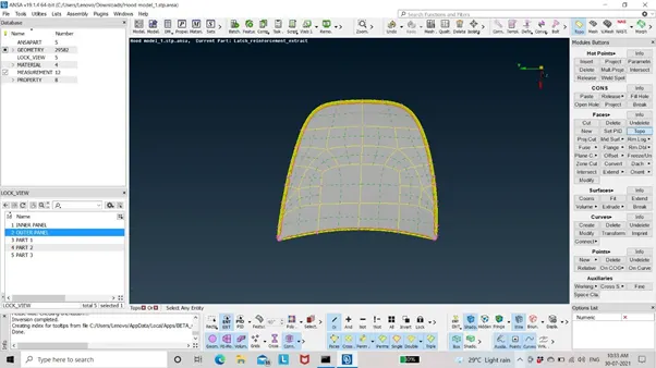
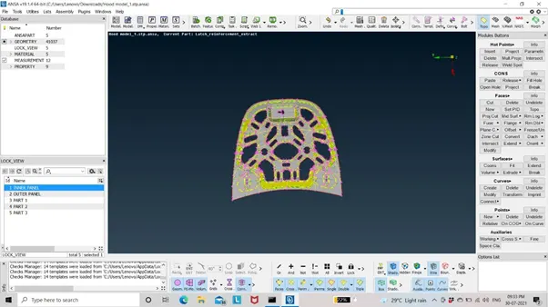
NOTE: Mid-surface can be easily generated by auto mid-surface but it is recommended to use manual method at initial stage for better understanding. Switch to hidden mode option to check whether mid-surface is created properly.
Use RmDBL to check symmetry of the model. If the model is symmetry delete one part and generate mid-surface and meshing on one part then use transform option to mirror the other part. This will save time.
RmDBL→ SELECT THE WHOLE MODEL→OK
TRNASFORM→COPY→SELECT THE ONE PART OF THE MODEL→CONFIRMATION (MIDDLE MOUSE)→DEFAULT SYMMETRY→APPLY→OK.
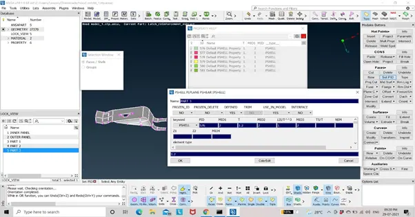
6) Set PID to the generated mid-surface.
FACES→SET PID→SELECT THE MID-SURFACE→PROPERTY CARD→RIGHT CLICK→NEW→ASSIGN THICKNESS→UNIQUE ID→COLOR→OK.
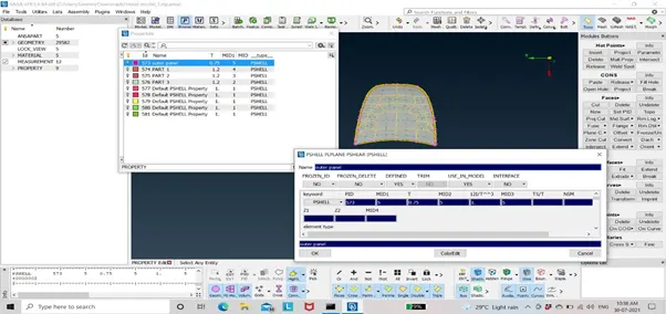
7) Define material to the created mid-surfaces.
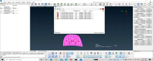
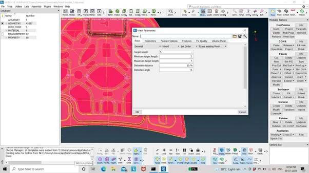
8) Now, before creating mesh set the mesh parameters.
MESH PARAMETERS→SELECT MESH TYPE, ELEMENT TYPE AND ORDER OF MESH→SPECIFY PARAMETERS (TARGET LENGTH, MIN. AND MAX. LENGTH) →OK
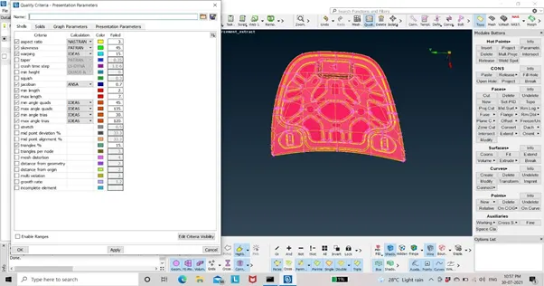
9) Assign quality criteria.
PRESS F11→SHELLS→ASSIGN DIFFERENT QUALITY PARAMETERS→APPLY→PRESENTATION PARAMETERS→ALL DETAILS→ELEMENT %→APPLY→OK.
9) For generating mesh. Switch to mesh mode. First measure the perimeter element value. Select the generated mid-surface and give perimeter length.
MESH→LENGTH→SELECT MID-SURFACE→CONFIRM→SPECIFY THE LENGTH→OK.
10) Measure the perimeter element length at the critical areas like fillet, features etc. If it is not satisfying the specified perimeter length then defeature it so that those elements will not fail in mesh quality.
11) Check the number of nodes at the circle. It should be positive to get good mesh flow.
NOTE: Always mesh the features and critical area first.
12) Now, create a mesh.
MESH→MESH GENERATION→BEST→SELECT FACE→CONFIRM.
To verify the mesh quality switch to hidden mode and improve the mesh quality by using modules like reconstruct, split, smooth, paste etc.
Hence, mesh is created.
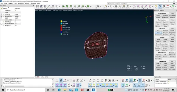
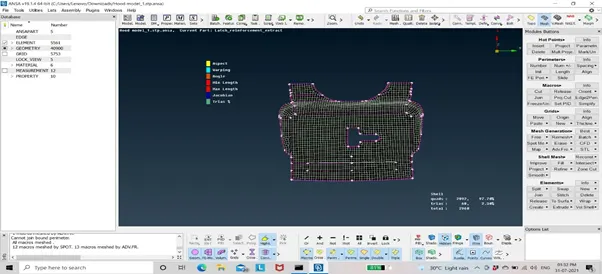
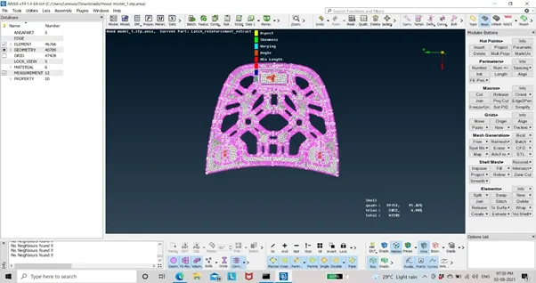
Tick the draw shell as solid option.
F11→PRESENTATION PARAMETER →DRAW SHELL AS SOLID.
LEARNING OUTCOMES:1) Geometry cleanup: to remove triple cons, needle face and to generate a deleted face.
2)Mid-surface: To generate mid-surface manually by offsetting the face.
3) To create a good quality mesh flow for the analysis of the model.
CONCLUSION: Hence, the geometry is cleaned and mid-surface, meshing is generated for the given model.
TO VIEW THE MODEL:
https://drive.google.com/file/d/15rEkkFt4xtUL9pPCr5_RbpFWFpoZiCKE/view?usp=sharing.