Week 8:- 3D Finishing - Challenges 1
1)The 3D finishing process involves completing the design and making it ready for final simulation and 2D detailing.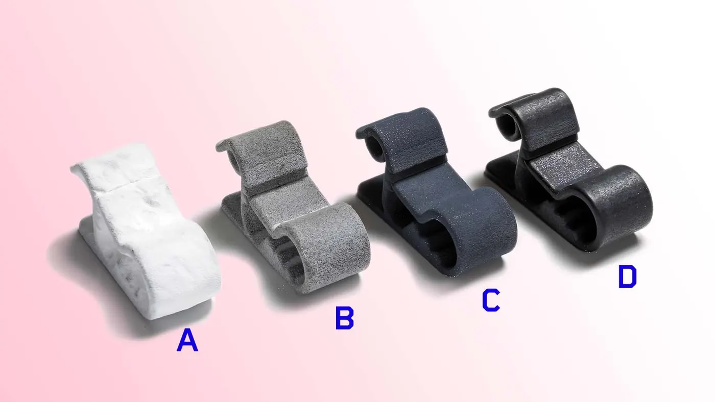
The following basic rules should be followed in 3D finishing:
1. The nominality of holes must be checked to ensure easy assembly of all the units.
2. Hole concentricity and sizes should be checked to ensure easy assembly of different parts.
3. The gaps between the different units should be checked to ensure the proper individual working of other units.
4. Fasteners should be implemented according to the hole size, and standard color codes should be applied as per customer requirements to differentiate the type of hole (simple hole, threaded hole, or counterbore hole).
- The standard colors used for holes are:
- Violet for Simple Hole
- Yellow for Threaded Hole
- Cream for Machined Area
- Cyan for Dowel Pin Hole
5. Renaming of the assembly and parts should be done to give each part a unique identity so everyone can identify which assembly the part belongs to.
6. After all the above steps, the model is sent for simulation and 2D detailing.
2)The following points are taken into consideration while finishing the design:
1. Hole Concentricity & Hole Sizes: All parts are to be checked for hole concentricity to ensure easy assembly during the finishing process.
2. Machining Area: The machining area in every part should be defined and highlighted using standard color codes.
3. Nominality: All unit dimensions should be maintained nominal to facilitate easy assembly of the unit.
4. Hole Coloring Standard: Color codes as per customer requirements should be applied in the 3D finishing. The standard colors are:
- Violet for Simple Hole
- Yellow for Threaded Hole
- Cream for Machined Area
- Cyan for Dowel Pin Hole
5. Pneumatic Layouting: The pneumatic layout, which involves the collection of different pneumatic pipes functioning as inlets to the pneumatic cylinder, should be done properly for the proper functioning of the units.
6. Gaps Checking: Proper gaps should be maintained between units to avoid clashes between different units.
7. Fasteners Implementation: Fasteners should be implemented in all units as per the requirement and load on the part.
8. Mylar Splitting as per Panel Profile: Mylar splitting should be confirmed while finishing the design. This should be done according to the thickness and shape of the panel used in the fixtures.
9. Proper Renaming of Parts/Assemblies as per Standard: Proper renaming of parts and assemblies should be done while finishing the design to ensure each part can be easily identified with unique identification.
3)
A rough locator is a part designed to guide the operator in positioning the car panel onto the pins accordingly. A rough locator can be a standard part or a custom-made part.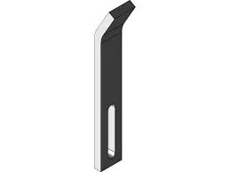
Uses of Rough Locators:
1. Assisting in Workpiece Location: Rough locators are used to help locate workpieces in the automation process. Locating refers to the desired position where the workpiece should be when it is being worked on, whether by a person, team, or robot.
2. Ensuring Accuracy: The accuracy of the locating components directly affects the consistency and quality of the final product. This is why these components are essential to your setup.
3. Foolproofing Method: Rough locators can also be considered a foolproofing method. Due to the rough locator, the part cannot be loaded in an incorrect position. The rough locators are set according to the angle of the respective panel, ensuring the part can only be loaded in the defined direction and orientation.
4)Points to Consider While Designing the Rough Locator
1. Placement at Panel Edges: The rough locator should be placed at the edges of the car panel it needs to guide.
2. Angle and Distance: The rough locator should be positioned at the same angle as the car part edge, with a minimum distance of 2-5 mm from the edge of the car part.
3. Guidance Direction: The rough locator should guide the panel in the direction of pin arresting.
4. Early Guidance: The rough locator should start guiding the panel 10 to 15 mm before the start of pin engagement.
5. Entry Angle Design: The rough locator should be designed with an entry angle for the car panel, generally ranging between 30 and 45 degrees.
6. Adjustment Slots: The rough locator should be designed with two slots to allow easy adjustments.
7. Slot Direction: The slots should be aligned in the direction of the car part guiding.
5)Gun Study Process
Welding is a predominantly used process in the automobile industry, with continuous development being a key requirement. In Body in White (BIW) production, complex steel structures, including sheets ranging from 300mm to 500mm with intricate shapes, are assembled through welding. The first step before starting the design of a welding fixture is to determine the spot weld locations. The location and orientation of other critical units of the fixture, such as clamps and locators, are decided based on the weld spot distribution.
The above image shows the weld gun used for spot welding, the weld matrix, and the weld locations where welding is to be done. There are two different types of weld points: geo weld points and respot weld points. Geo weld points are welded in the first stretch, and respot weld points are done in the second go.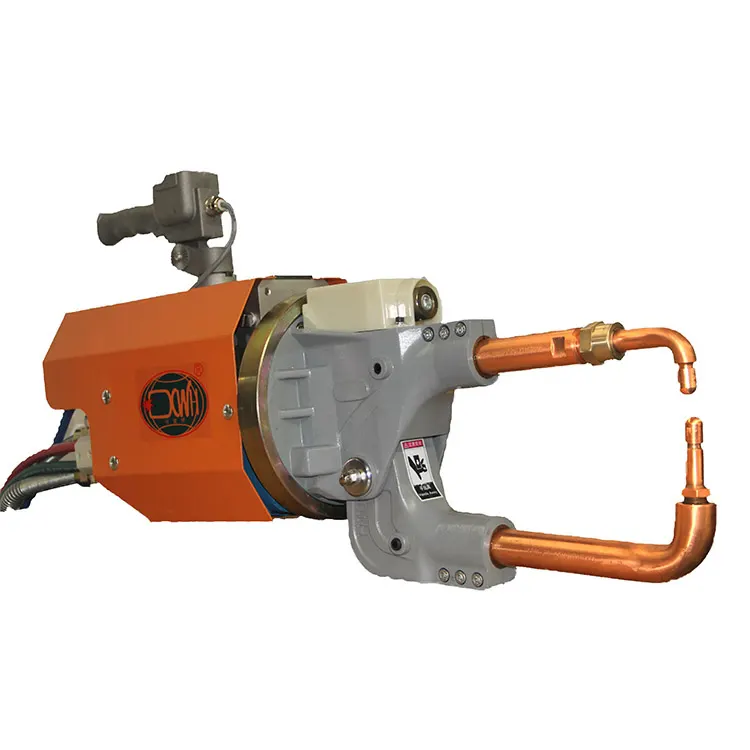
Typical Weld Gun
The gun study involves examining the weld gun (a portable device for semiautomatic welding of parts of various articles) that will be used for the operation, depending on the size and thickness of the part.
In the weld gun study, the weld gun to be used for spot welding is checked over the panel using 3D software. The fixture is designed to hold the car panel in position, and the weld gun position is checked over the predefined spot weld points to determine whether the gun interferes with the fixture unit. If the weld gun interferes with the fixture unit, redesigning or repositioning of that unit is done and reconfirmed to ensure the gun does not interfere. Fixtures are redesigned if the gun interferes with the fixture unit, while the weld spot positions remain the same.
6) Points to Consider During the Gun Study
Weld gun study is a very time-consuming process, and the entire welding cycle time study depends on the number of weld spots.
The following points need to be considered during the gun study:
1. Weld Spot Axis: The axis of the weld spot along the welding direction must be normal to the weld surface.
2. Number of Weld Spots: The number of weld spots for the panel and the time required to spot each weld determine the total time required to complete all the weld spots.
3. Device Models Programming: If there are one or more device models to program, the behavior of each model in the work cell can be simulated over time. Instructions for each device are coded by providing sequences. The sequence defines the motion, manipulation, and action of the devices. Based on the distance of each tag point from the home position, motion type, speed, and acceleration, one can obtain the cycle time for each device assigned with sequences. This way, robot cycle time is precisely calculated.
4. Collision Check: After sequencing all the devices, a simulation is run with the "collision check" enabled to ensure that the welding operation is collision-free.
7) Pneumatic Routing
Pneumatic systems should be efficient and leak-free. However, sometimes they are not due to improper tube line routing, which can result from a lack of knowledge or shortcuts taken during planning.
Planning tube line routing is a time investment that can yield a significant return on investment (ROI), especially for complex systems. During system design, routing should be developed as the next step after sizing the tube lines and selecting the appropriate fittings.
Here are some guidelines for effective pneumatic routing:
1. Accessible Fitting Joints: Leave fitting joints as accessible as possible. Inaccessible joints are difficult and time-consuming to assemble, tighten, and service.
2. Use Software Tools: Utilize software tools to perform labor-intensive calculations, such as pressure drop.
3. Employ U-Bends: Use U-bends to allow for line contraction and expansion.
4. Include Offset Bends: Incorporate offset bends to accommodate motion under load, regardless of how ‘rigid’ the system seems.
5. Favor Bends Over Straight Lines: Opt for bends rather than straight tube lines. A straight line tube assembly with no bends can cause joint strain, leading to leaks.
6. Allow Room for Assembly: Ensure the routing design provides space for assembling any required connections.
7. Minimize Pressure Drop: Reduce pressure drop by avoiding obstructions with as few 90° bends as possible. Note that one 90° bend causes more pressure loss than two 45° bends.
8. Avoid Critical Areas: Route lines around rather than over areas that require regular access or maintenance.
9. Design with Clamping in Mind: Proper design facilitates appropriate clamping. It’s often possible to clamp several lines together.
10. Focus on Troubleshooting and Maintenance: Keep troubleshooting and maintenance in mind by focusing on logical design and avoiding crossed lines.
11. Prevent Physical Damage: Design the tube line routing to reduce the likelihood of users standing or climbing on the plumbing.
8)Solenoid Valve
A solenoid valve is an electromechanical valve. Solenoid valves vary in the characteristics of the electric current they use, the strength of the magnetic field they generate, the mechanism they use to regulate fluid, and the type and characteristics of the fluid they control. The mechanisms can range from linear action, and plunger-type actuators to pivoted-armature actuators and rocker actuators. The valve can use a two-port design to regulate flow or a three or more-port design to switch flows between ports. Multiple solenoid valves can be placed together on a manifold. Solenoid valves are the most frequently used control elements in fluidics. Their tasks are to shut off, release, dose, distribute, or mix fluids. They are found in many application areas, offering fast and safe switching, high reliability, long service life, good medium compatibility of the materials used, low control power, and compact design.
Components of a Solenoid Valve
1. Valve Body: This is the main body of the valve to which the solenoid valve is connected. It is usually integrated into the process flow pipeline to control the flow of fluids like liquid or air. The flow is ordinarily controlled by a handle, but in the case of an automatic valve, the solenoid valve takes over this function.
2. Inlet Port: This is the port through which the fluid enters the automatic valve, allowing it to enter the final process.
3. Outlet Port: The fluid that passes through the automatic valve exits through the outlet port. The solenoid valve controls the flow of fluid from the inlet port to the outlet port, which is eventually connected to the process where the fluid is needed.
4. Coil/Solenoid: The solenoid coil body is cylindrical and hollow inside, covered with a steel finish. Inside the solenoid valve is the solenoid coil.
5. Coil Windings: The solenoid consists of several turns of enameled wire wound around ferromagnetic material like steel or iron. The coil forms a hollow cylinder, externally covered with steel, with a plunger or piston inside. The plunger's motion is controlled by a spring.
6. Lead Wires: These are the external connections of the solenoid valve, connected to the electrical supply. When the solenoid valve is energized, current flows through these wires to the solenoid valve, and when de-energized, the current stops.
7. Plunger or Piston: This is a solid, cylindrical metallic part placed inside the solenoid valve's hollow portion. When electrical current passes through the solenoid valve, a magnetic field is generated inside the hollow space, causing the plunger to move vertically. When the current stops, the magnetic field ceases, and the plunger remains in place due to the spring's force.
8. Orifice: The orifice is a crucial part of the valve through which the fluid flows. It connects the inlet and outlet ports. In ordinary valves, the orifice is covered by the valve disc at the bottom of the valve stem, controlled by a handle. In solenoid valves, the plunger controls the orifice's opening, which is further controlled by the spring and the current flowing through the solenoid valve.
Basic Working of a Solenoid Valve
Initially, a sensor detects the process requirement on the outlet side of the solenoid valve. When it senses that a certain fluid flow is needed, it allows current to pass through the solenoid valve. This energizes the valve and generates a magnetic field, triggering the plunger's movement against the spring's action. The plunger moves upwards, opening the orifice and allowing fluid to flow from the inlet port to the outlet port.
If the current remains constant, the plunger's position and the orifice's opening stay the same. If the sensor detects a need for more fluid flow, it increases the current, creating a stronger magnetic field and more upward motion of the plunger, further opening the orifice. Conversely, if less fluid flow is needed, the sensor allows less current to pass.
When the sensor determines that no more fluid is required, it stops the current flow to the solenoid valve. The valve de-energizes, and the plunger moves to the bottom position, closing the orifice and blocking the fluid flow.
In this way, the solenoid valve operates automatically, opening to the required extent when fluid flow is needed and closing entirely when it is not.
9)Valve Bank
A valve bank is an arrangement of multiple solenoid valves. A valve bank typically features a common inlet port, a single servo line to each pneumatic valve, and independent vent passages for each solenoid. On the solenoid bank, each solenoid valve separately controls the feed of high-pressure servo air to a single pneumatic valve. The valve is actuated by selectively energizing the corresponding solenoid to allow servo air to the servo port of the valve. To return the valve to its fail-safe position, the solenoid is de-energized to vent the servo port of the valve to ambient.
Common Features of a Valve Bank
- Designed for High Vibration Levels: Valve banks are built to withstand high levels of vibration, ensuring durability and reliability in demanding environments.
- Lightweight Construction: They use aluminum alloy manifolds for a lightweight design, which is advantageous for various applications.
- High-Temperature Environments: Valve banks are designed to operate effectively in high-temperature environments.
- Flexible Design Architecture: The design architecture allows for easy selection of two to six solenoid valves, providing flexibility and adaptability for different needs.
10)Sensor and Its Application in Automation
A sensor is a device that detects or measures a physical property and records, indicates, or otherwise responds to it. A unit designed to sense car panels using electrical sensors is called a sensor unit. The data from the sensors are sent to the PLC (Programmable Logic Controller) so the next process can be executed based on this signal. Sensors are very sensitive and easily damageable, so a sensor cover is provided for protection.
Sensors in Automation
In industrial automation, sensors play a crucial role in making products intelligent and highly automatic. They allow for the detection, analysis, measurement, and processing of various changes, such as position, length, height, appearance, and displacement that occur in production sites. Sensors also play a significant role in predicting and preventing future events, thus catering to various sensing applications.
Types of Sensors Used in Industrial Automation
- Proximity Sensors: Detect the presence or absence of an object within a certain range.
- Vision Sensors: Capture and process visual information.
- Ultrasonic Sensors: Measure distance by using ultrasonic waves.
- Position Sensors: Determine the position of an object.
- Photoelectric Sensors: Detect objects, changes in surface conditions, and other events through light.
- Temperature Sensors: Measure temperature.
- Inclination Sensors: Measure the angle of tilt or inclination.
Applications of Sensors
Sensors have broad applications in industrial automation, including:
- Motion Control: Position sensors are used to control the movement of robots.
- Tank-Level Sensing: Ensures accurate measurement of fluid levels in tanks.
- Semiconductor Process Equipment: Sensors ensure precision and reliability in semiconductor manufacturing.
For example, displacement sensors are used for the precision positioning of objects at the nanometer level and in measuring the precise thickness of disk drives, assembly line testing, and machine tool metrology. They are widely used in machining to ensure high accuracy and quality.
11)Types of Sensors
Below is a list of different types of sensors commonly used in various applications, each measuring a different physical property:
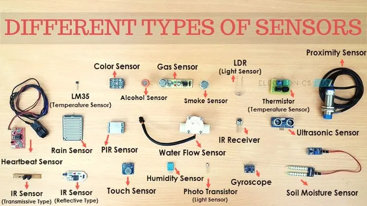
1. Temperature Sensor
2. Proximity Sensor
3. Accelerometer
4. IR Sensor (Infrared Sensor)
5. Pressure Sensor
6. Light Sensor
7. Ultrasonic Sensor
8. Smoke, Gas, and Alcohol Sensor
9. Touch Sensor
10. Color Sensor
11. Humidity Sensor
12. Tilt Sensor
13. Flow and Level Sensor
12) Fundamental Points to Consider When Designing or Selecting Sensors
1. Sensor Unit Design: The sensor unit is designed to sense the car panel using electrical sensors.
2. Signal to PLC: The signal from sensors is fed to the PLC, which triggers the next process.
3. Confirmation of Presence: Sensors are used to confirm the presence or absence of a panel/component.
4. Error Prevention: Sensors should help to avoid human errors in the process.
5. Matching Sensor Count: The number of sensors should match the number of panels in the assembly. For example, if there are 9 panels in an assembly, there should be at least 9 sensors used.
6. Adjustable Mounting: Sensors should be designed with slots for adjustment in three directions.
7. Operator Safety: Sensors should provide safety features for the operator.
8. Types of Sensors Used: Typically, proximity sensors, laser sensors, and photoelectric sensors are used in fixtures.
9. Manufacturers: Major sensor manufacturers include IFM, Pepperl+Fuchs, SICK, OMRON, etc.