Week 8:- 3D Finishing Challenge 2
Aim:To Perform 3D finish and create Rough locators for the Assembly design created for the given Panel.
Software Used:CATIA-V5
Panel given: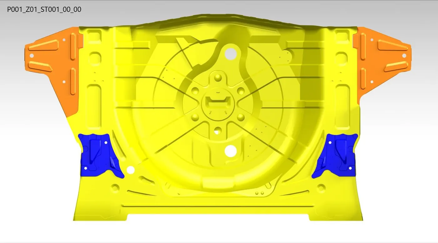
Introduction:
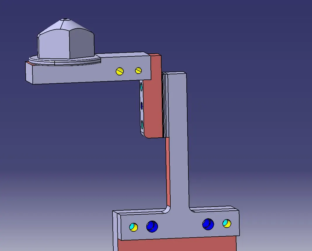
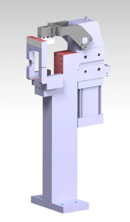
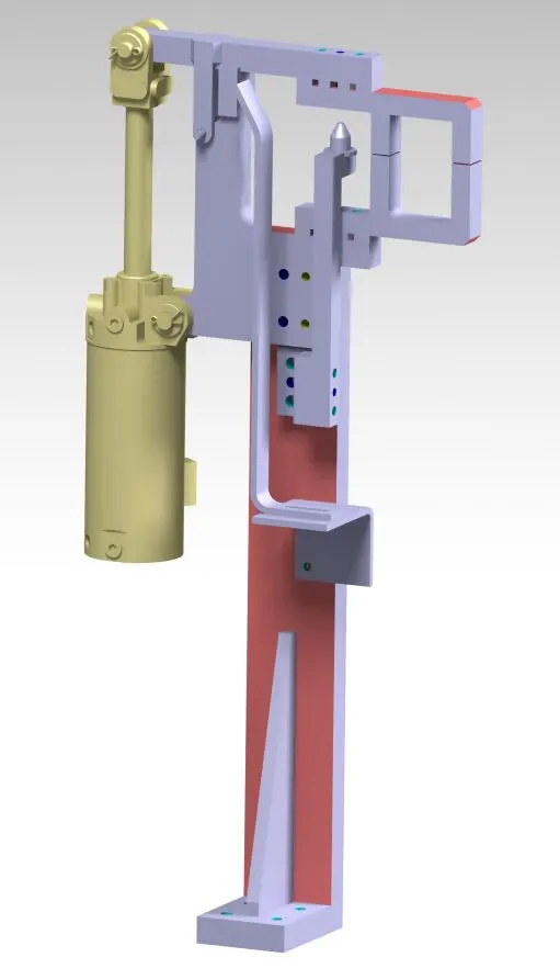
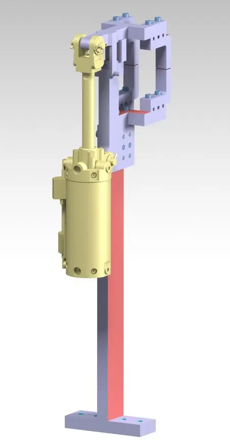
3D-Finishing:It is the process before sending the part for final simulation.The part should be checked for all proper clearences and representing the maching sides of a part by applying colour codes.In this process the part is checked with hole concentricity,designing of rough locators for guiding the panel.Fasteners are implemented as per the hole size & the standard color codes as per the customer requirement are applied to differentiate the type of hole,wheather its Dowel hole, threaded hole or Clearance hole.Renaming of the assembly & the part is done to give every part a different identity so everyone can identify in which assembly this part is going to be fit.After doing all these things the model is sent for simulation & 2D detailing.
Rough Locators & its Use:
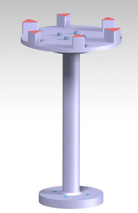
Rough locators are used to help locate workpieces in the automation process. Locating refers to the desired location where you want the workpiece to be when it is getting worked on either by a person, team, or robot.It is a device to establish and maintain position of a part in a jig or fixture.They usually feature a 35mm bend at 60° with a height from bend ranging from 65mm to 320mm. The width of these locators are 19mm, 32mm depending upon the standard we are using.Rough locators are also work as Poka-yoke.Poka-yoke (ポカヨケ, [poka yoke]) is a Japanese term that means "mistake-proofing" or "inadvertent error prevention". A poka-yoke is any mechanism in any process that helps an equipment operator avoid (yokeru) mistakes (poka)..Rough locators are used to help locate workpieces in the automation process. Locating refers to the desired location where you want the workpiece to be when it is getting worked on by a person.The accuracy of the locating components directly affects the consistency and how the final product will come out.It can be called as fool proofing method also.Fool Proofing is a method by which ensures that the workpiece will fit into the work holder only if the workpiece is placed in the correct position. Because due to the rough locator the part cannot be loaded in incorrect position.The rough locators are set according to the angle of the respective panel hence part can only be loaded in defined direction & orientation.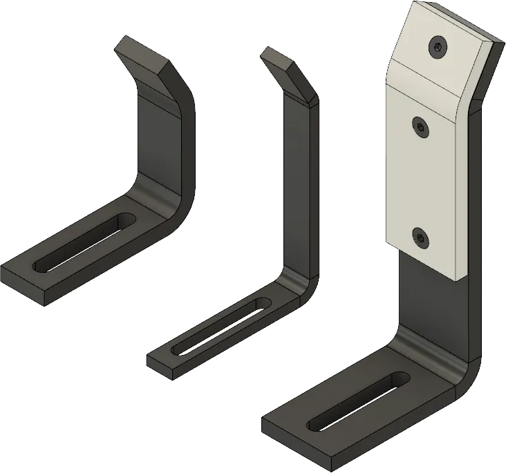
Gun study:
Welding is predominantely used in automobile industries and requirements for fixtures that ease the welding process is a continuous development
task in any industry.Car Body-In-White (BIW) is a complicated steel-structure including 300~500 sheets with complex shape and are assembled by means of welding in a high rhythm through 55~75 robotic work-stations.The foremost step taken before starting the design of welding fixture is to arrive at the spot weld locations. The location and orientation of other critical units of the fixture including clamps, locators etc., are decided based on the weld spot distribution. The weld spots for Front door inner panel Side bracket assembly are located as shown in Table 1 with respect to the body line of car.It includes the study of the weld gun (A portable device for semiautomatic welding of parts of various articles) which is going to be used for the operation depending on the size of the part, Thickness of the part etc.It includes the study of the weld matrix & the weld point positions. There are two types in weld point one is geo weld points which ensures the geometry of the assembly & second is the Re spot weld points which adds strength to the already welded part.
The device used to make sopt welding on the panel is called Gun.The Gun may differ depending upon the application.Fixtures will be designed by considering the weld spots on the panel.After designing the Fixture the CAD file of the gun be placed on the weld spots to check wheather the Gun is clearences with the Fixture.After adjusting the Fixtures the cordinates of the welds be taken for further operations of Weld Gun. 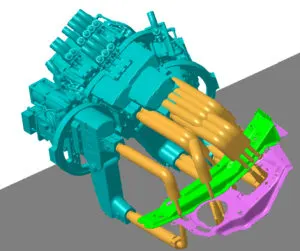
Overview of the Assembly:
Design Tree;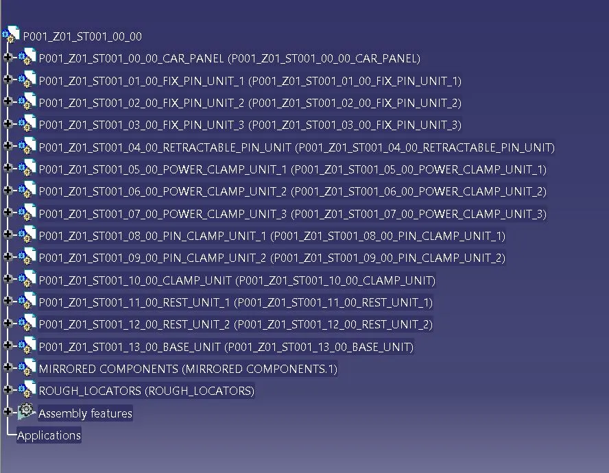
1.Pin Units:
- P001_Z01_ST001_01_00_FIX_PIN_UNIT_1
- P001_Z01_ST001_02_00_FIX_PIN_UNIT_2
- P001_Z01_ST001_03_00_FIX_PIN_UNIT_3
- P001_Z01_ST001_04_00_RETRACTABLE_PIN_UNIT
- P001_Z01_ST001_14_00_FIX_PIN_UNIT_4
- P001_Z01_ST001_15_00_FIX_PIN_UNIT.1
Positioning of Pin Units: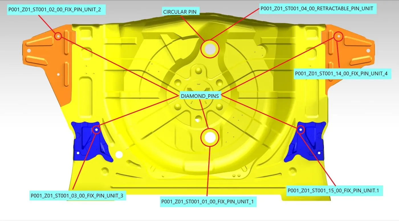
Design of Pin Units: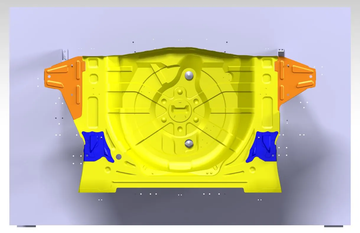
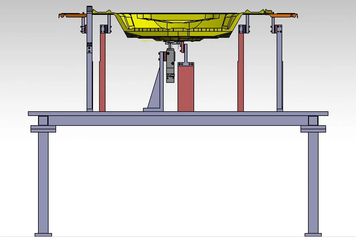
2.Power Clamp Units:
- P001_Z01_ST001_05_00_POWER_CLAMP_UNIT_1
- P001_Z01_ST001_06_00_POWER_CLAMP_UNIT_2
- P001_Z01_ST001_07_00_POWER_CLAMP_UNIT_3
- Symmetry of P001_Z01_ST001_05_00_POWER_CLAMP_UNIT_1.1
- P001_Z01_ST001_18_00_POWER_CLAMP_UNIT_4
- P001_Z01_ST001_19_00_POWER_CLAMP_UNIT
Positioning of Power Clamp Unit: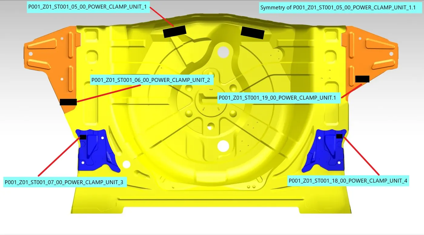
Design of Power Clamp Units: 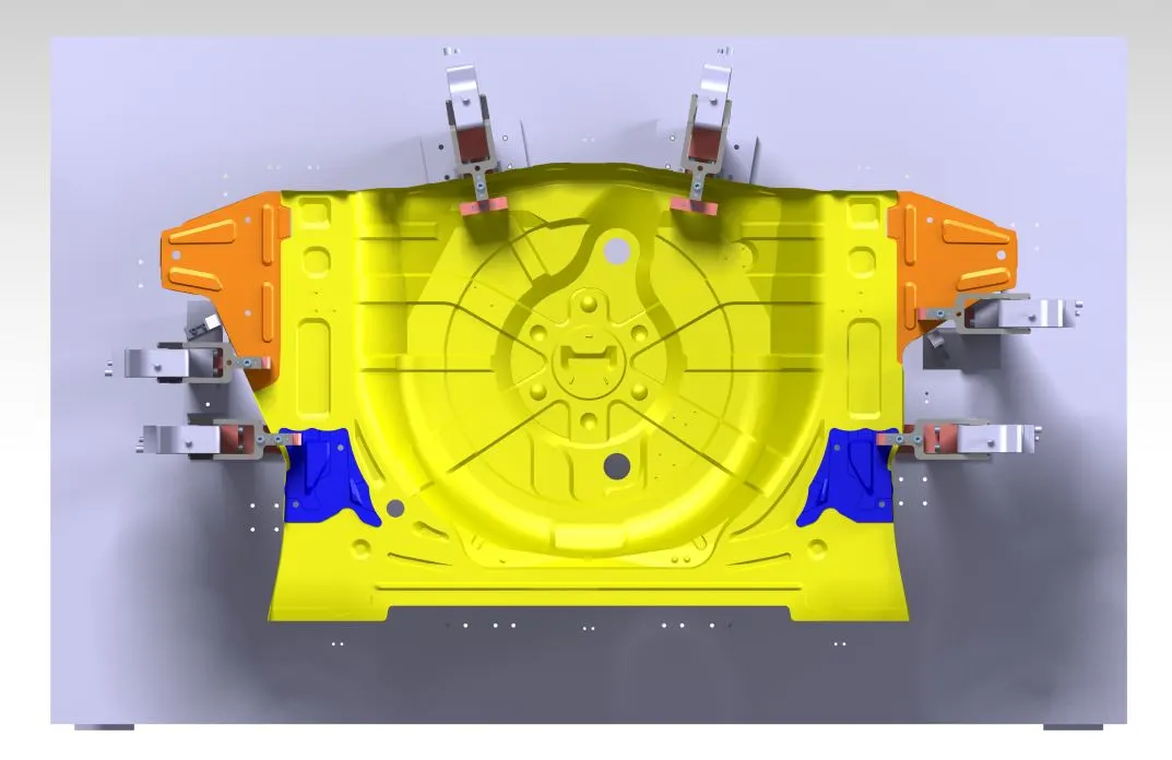
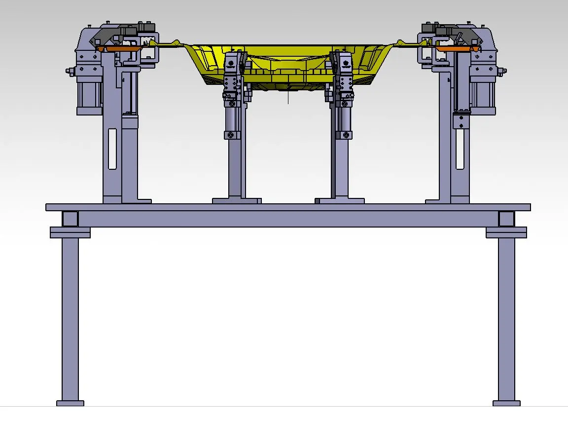
3.Pin Clamp unit:
- P001_Z01_ST001_08_00_PIN_CLAMP_UNIT_1
- P001_Z01_ST001_09_00_PIN_CLAMP_UNIT_2
- P001_Z01_ST001_16_00_PIN_CLAMP_UNIT.1
- P001_Z01_ST001_17_00_PIN_CLAMP_UNIT.1
Positioning of Pin-Clamp Units: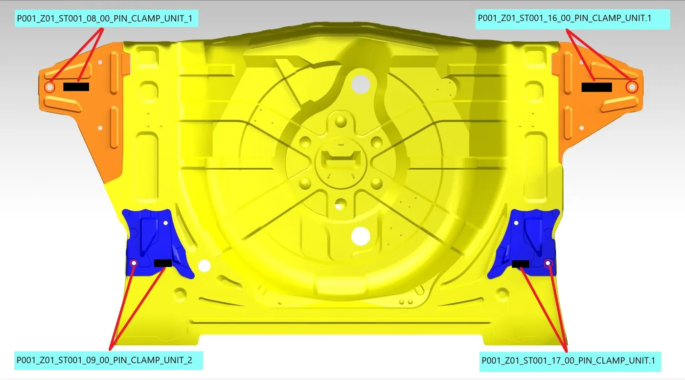
Design of Pin-Clamp Unit:
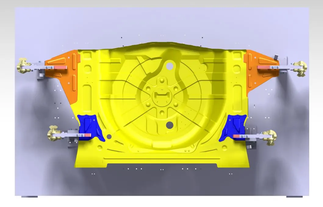
4.Clamp Unit:
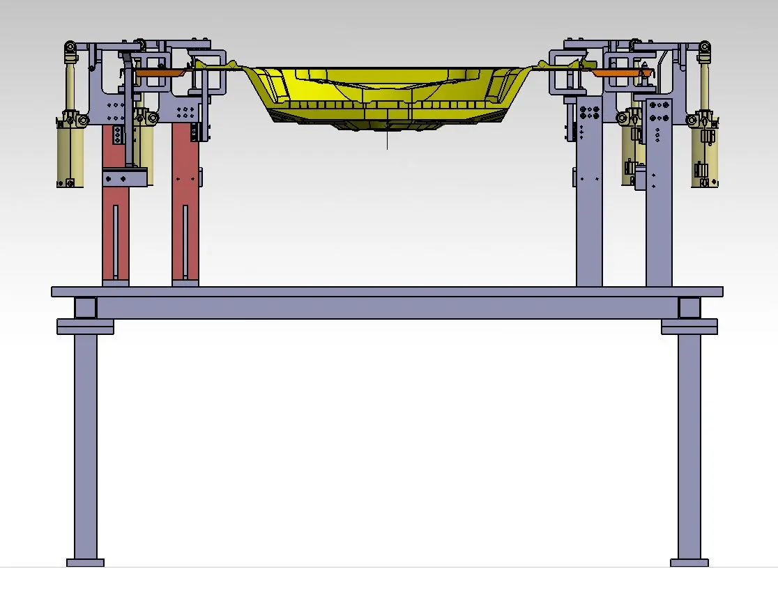
- P001_Z01_ST001_10_00_CLAMP_UNIT
- Symmetry of P001_Z01_ST001_10_00_CLAMP_UNIT.1
Positioning of Clamp Unit: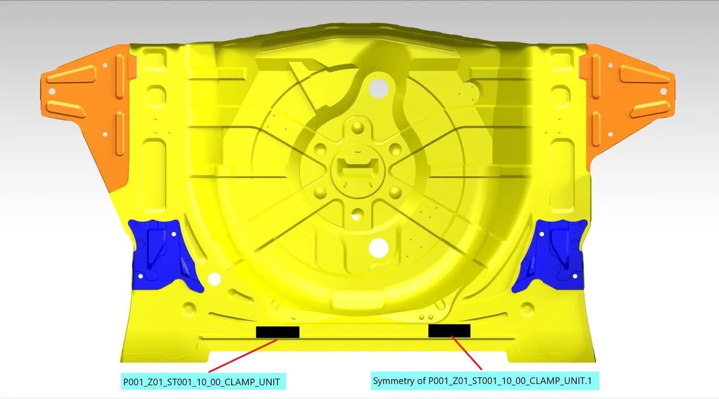
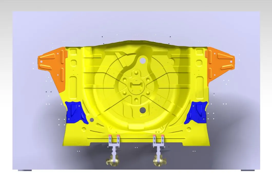
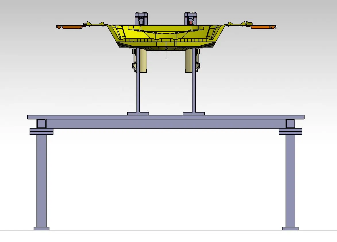
Design of Clamp Unit:
5.Rest Units:
- P001_Z01_ST001_11_00_REST_UNIT_1
- P001_Z01_ST001_12_00_REST_UNIT_2
- Symmetry of P001_Z01_ST001_12_00_REST_UNIT_2.1
Positioning of Rest Unit: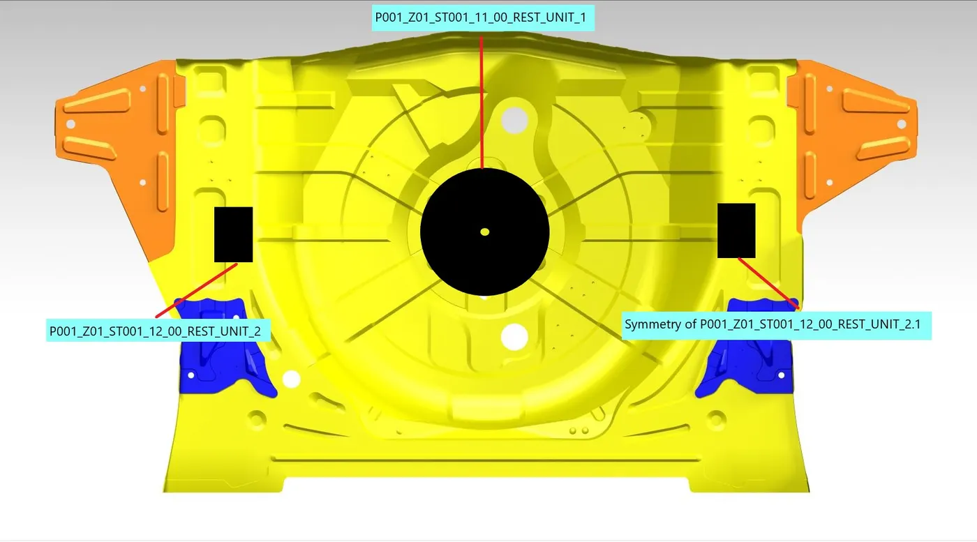
Design of Rest Units: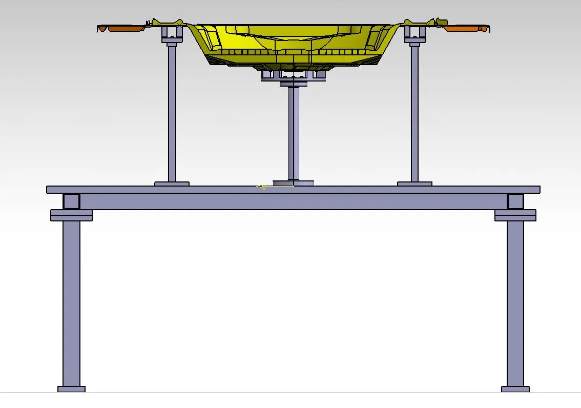
6.Base Unit:
- P001_Z01_ST001_13_00_BASE_UNIT
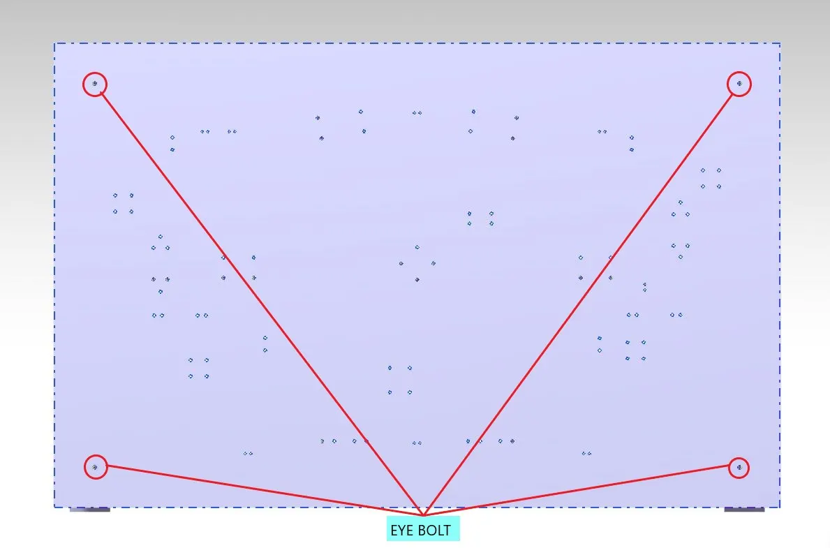
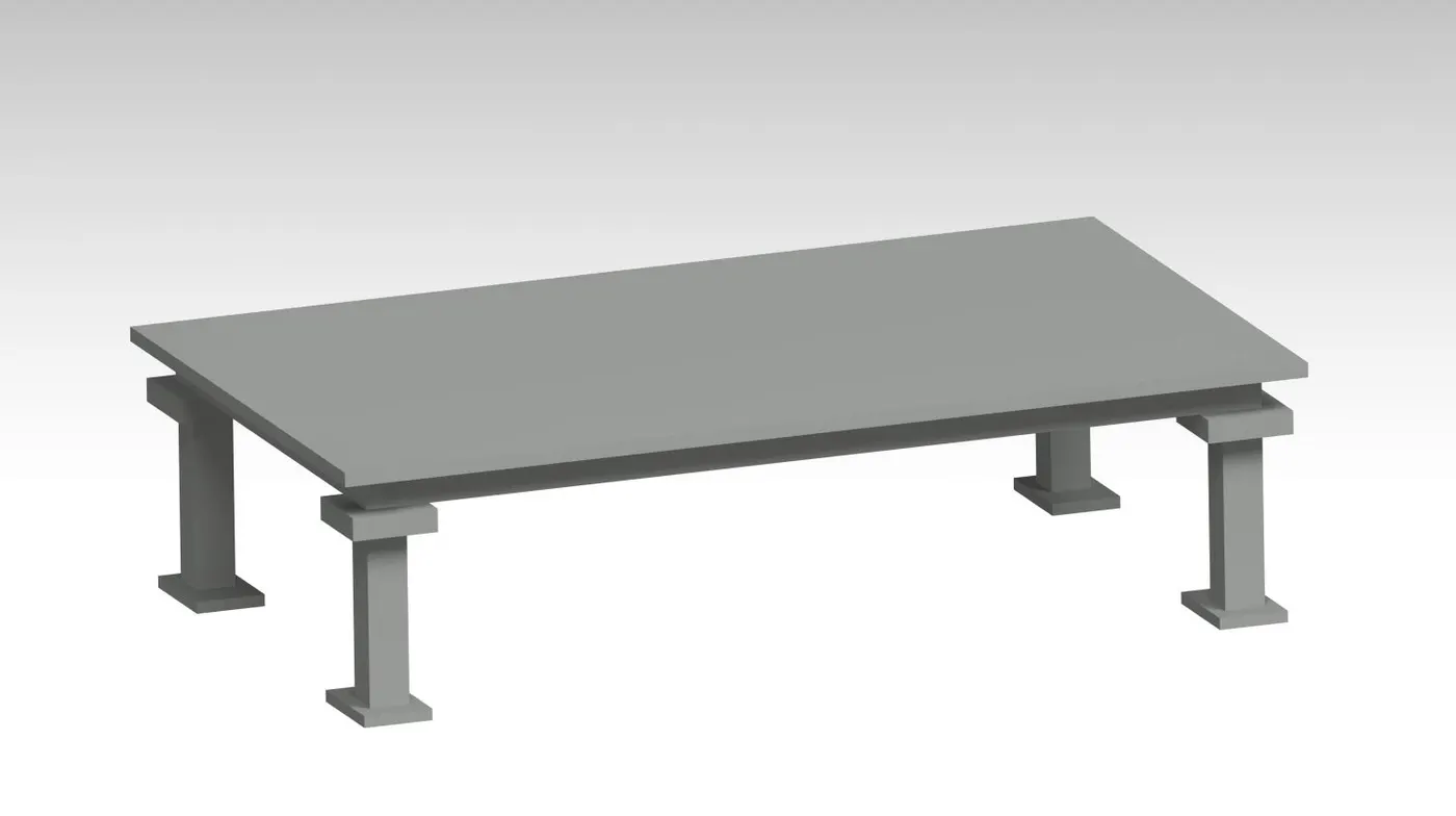
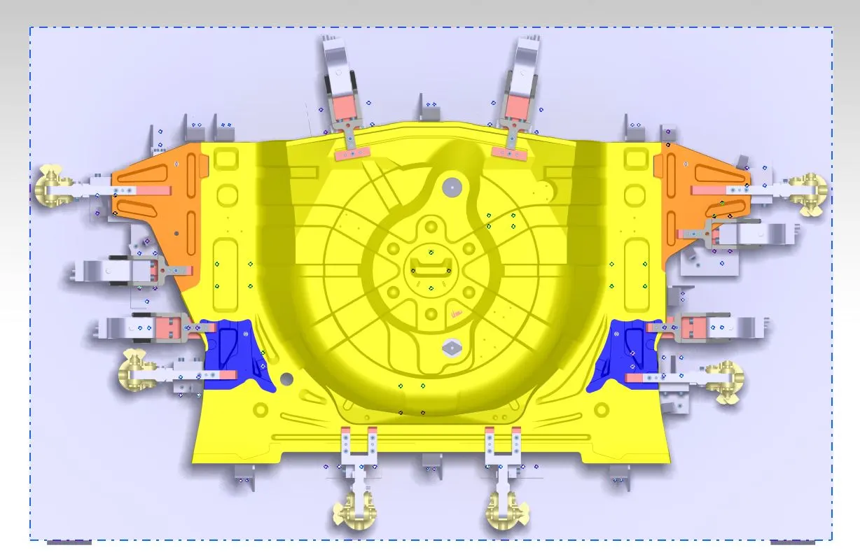
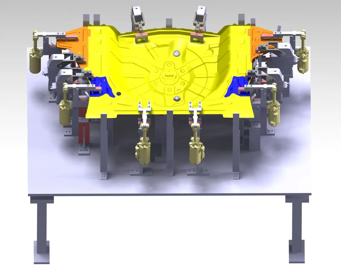
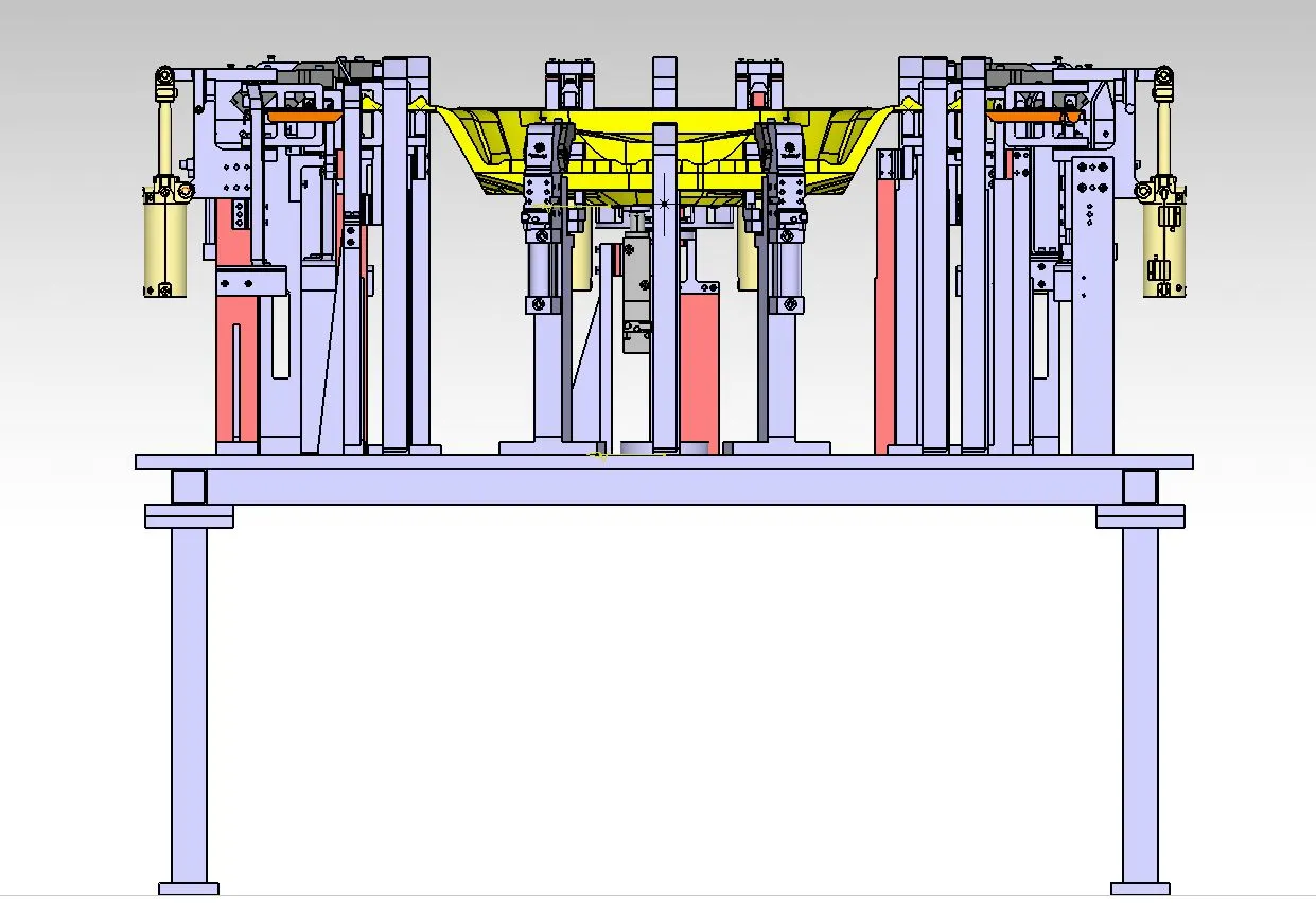
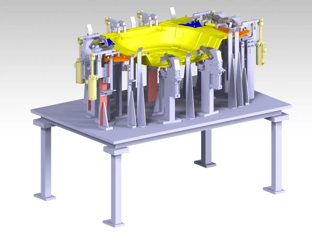
Overall Assembly of Fixtures:
3-D Finishing of Fixtures:
Colour CODES: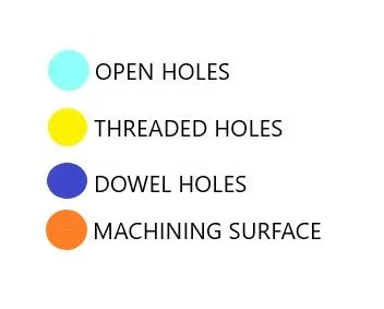
Fixures after 3D Finishing: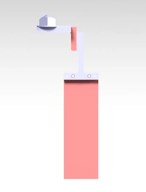
Rough Locators:
Postioning of Rough Locators: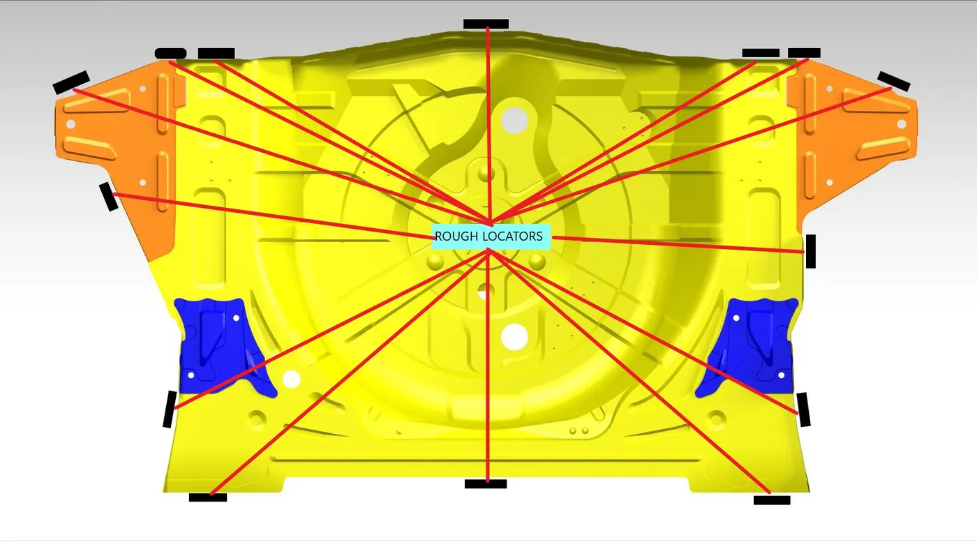
Design of Rough Locators: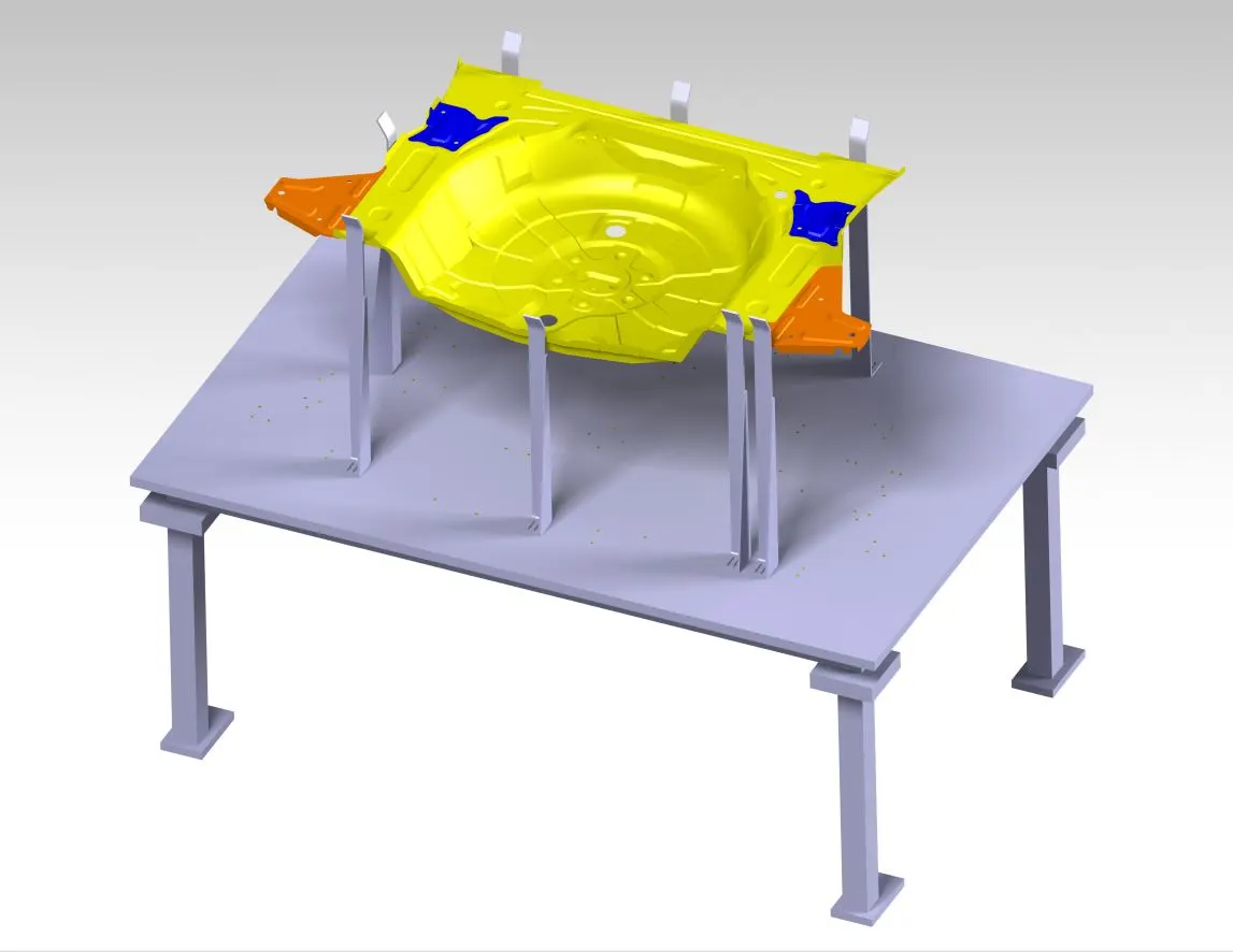
Conclusion:Hence,3-D finishing is performed on the designed Assembly of Fixtures and Rough Locators were designed for the given panel.