Week 8:- 3D Finishing Challenge 2
Theory:
3D Finish
3D finish is a process where the design is being completely finish & to be ready for final simulation & 2D detailing.
Following points are taken into consideration while finishing the design.
- Hole concentricity & hole sizes
All parts hole’s concentricity & holes sizes are checked for easy assembly while finishing the parts.
- Machining area
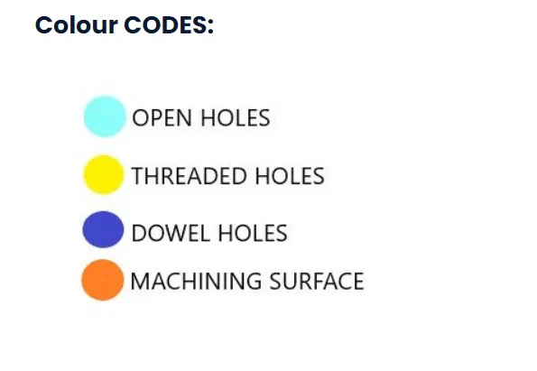
The machining area in every part is defined & the machining area is highlighted by using orange colour.
- Nominality
All units dimensions are maintained nominal to facilitate easy assembly of the unit.
- Holes colouring Standard
Color code standard used in the 3D finishing.
- Fasteners Implementation
Fasteners are implemented in all unit as per requirement & load on the part.
- Avoiding clash between different part
Proper maintained the gap between parts to avoid the clash
- Mylar Splitting as per panel profile
Mylar splitting are confirmed while finishing the design.
- Proper renaming of parts/assemblies as per standard-proper renaming of parts & assemblies are done while finishing the design hence we can identify each & every part easily with a unique identification.
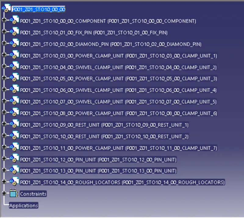
- Renaming & Structuring of the design tree:
- Renaming of the design tree is done. & Structuring design tree in way that its simple to identify the units. Some units use multiple time those are easy to identify by its name.
3-2-1 principle:-
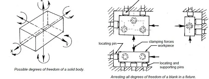
- The 3-2-1 method is a work-holding principle where three pins are located on the 1st principle plane, i.e., either XY, YZ, ZX. And two pins are located on the 2nd plane perpendicular to the 1st plane, and at last, one pin on the plane is mutually perpendicular to the 1st and 2nd planes.
- It represents the minimum requirement for the locating elements.
- The locators along with the clams which hold the part in place, provides equilibrium for all the forces.
- Stability is satisfactory if all three rest buttons are widely spaced and resultand cutting force lies within the triangular area between the buttons.
- If resultant cutting force lies outside the triangular area then it generates a moment which in turn lifts are overturns the component.
Locating Process in 3-2-1 method
We have two objectives when mounting a part in a fixture for machining
1. Accurately position the part at the desired coordinates.
2. Restrict all six degrees of freedom so that the part cannot move.
A widely used method of accomplishing these two objectives uses the 3-2-1 principle, so-called because it entails three steps that employ three, then two, then one fixed points of known location. Since that adds up to six fixed points, it’s also known as the six point method.
In the three steps of the 3-2-1 method, three mutually perpendicular planes, called datum planes, are introduced, one at each step. These three planes define the workpiece position, and together with opposing clamping forces fully constrain the part. Let’s take a look at the details of the 3-2-1 method
First Plane
Geometry tells us that three points are required to define a plane. This is the "3" in 3-2-1. So, three specific points are used to define the first plane. Fewer than three points cannot define a plane, and in the real world dimensional tolerances mean that four or more points will not be coplanar.
A real-world, less than ideally perfect part placed on four or more reference points will, in fact, rest on only three of the points due to its less than perfect surface. Different parts may rest on different combinations of three points, resulting in variation between finished parts. A stool can be used to illustrate this concept.
A two-legged stool would certainly be unstable. A three-legged stool sits rock-solid. A four-legged stool is often found to rock. In the illustration, a three dimensional part, represented by a cube, is placed on a datum plane defined by three support points.
The part’s six degrees of freedom have now been reduced to three. It can still move along the X or Y axes, and it can still be rotated about the Z axis. The part cannot move along the Z axis because it is held against the plane by clamping force.
Second Plane
A second plane, if it is perpendicular to the first, can be defined by two points, the "2" in 3-2-1.
The part is now constrained to one degree of freedom ,movement along the Y axis.
The part cannot move along the X or Z axes because it is held against the planes by clamping force.
Third Plane
A third plane, if it is perpendicular to both of the first two planes, can be defined by one point, the "1" in 3-2-1. The part is now entirely constrained. It cannot move along or rotate about the X, Y, or Z axes. (Remember that the part is held against each of the three planes by clamping force.
Base unit:
A base unit is the unit designed to mount all the other units of the tool, also other parts necessary for a tool like pneumatic valve box, trunking cable path will also be mounted on to a base unit.
Below are the some parts of a base unit in general.
- Trunking channel
- base plate
- Valve box
- Measuring hole cover
- Eye bolt.
- Pedestal.
- Weld Bars.
- Floor plate.
Typical parts of a base unit:
Base unit :
Base plate is a machined plate of 20 to 40mm thickness made of steel and aluminum on to which the holes are drilled to mount the individuals’ units like clamp units. Pin units etc. of a tool.
There are three key benefits to a base plate;
- They can help to quickly and accurately tram in fixtures and vises.
- They can hold large, complicated, or odd- Shaped parts.
- They protect the cast iron machine table.
Pedestal:
A pedestal is a part which connects the base plate to the floor plate. A pedestal is a standard part in general, & in some cases it can be a welded frame integrated with the base plate.
A standard pedestal can be of different heights and different sizes.
Depending on the size of the base plate, the number of pedestal varies for load distribution.
A pedestal are of different types with different inclinations.
Trunking Channel:
Trunking channel is a standard part which will accommodate all the pneumatic & electrical hoses and wires for the units. The trunking channel includes all the pressure inlet cables going to the pneumatic parts of the fixture & protect them from damaging while operation is in process.
Valve Box:
Valve box is a standard part which will contain all the valves for the pneumatic units. The valve box is the box which includes different solenoid valves. The pneumatic fixture work on air pressure provided to it. So, the arrangement of air pressure inlet & outlet is done within this valve box. The trunking channel includes all the pressure inlet cables going to the parts of the fixture and protects them from damaging while operation in process.
Eye Bolt :
An eye bolt is a bolt with a loop at end one. They are used to firmly attach a securing eye to a structure, so that ropes or cables may them the be tied to it.
Machinery eye bolts are fully threaded and may have a collar, Making them suitable for use with angular loads up to 45 degree. Eye bolts without a shoulder should not be used for angular loads. Heavy forged eye bolts with a continuous eye may be forged with an integral shoulder. allowing their use for heavy off-axis loads.
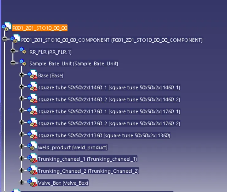
- Renaming parts & Structuring design Tree:
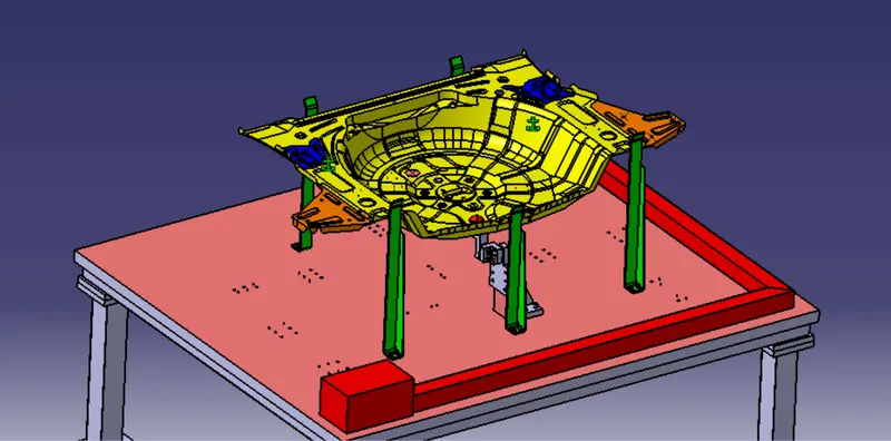
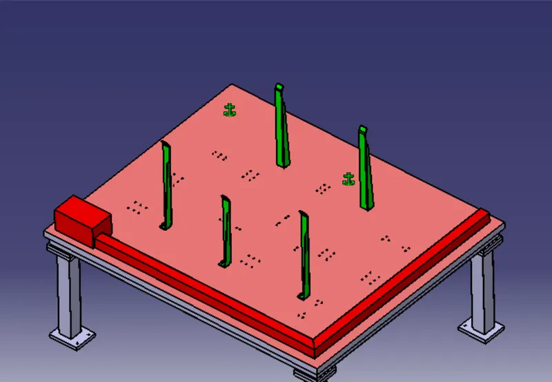
- Positioning Of Rough Locators on the base plate:
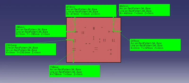
- Hole Made to nominal base plate.
Rest Unit:
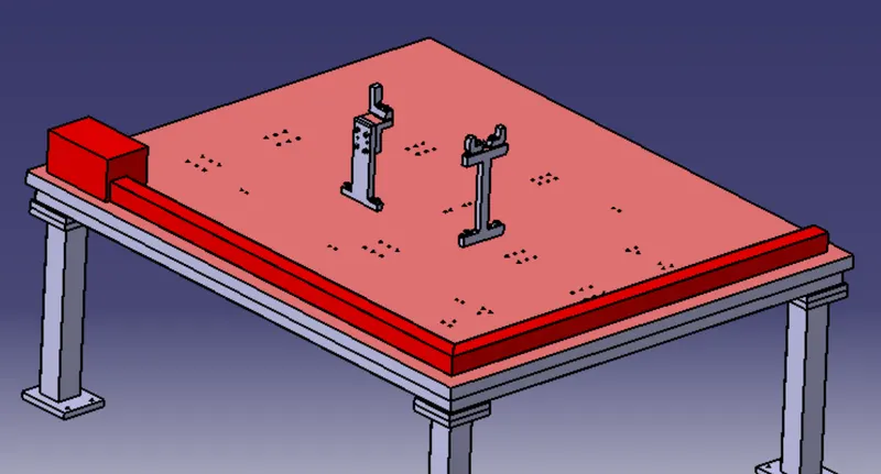
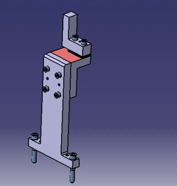
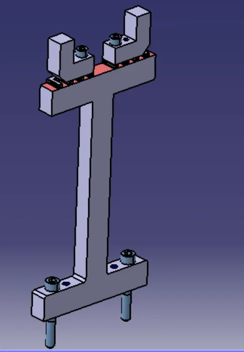
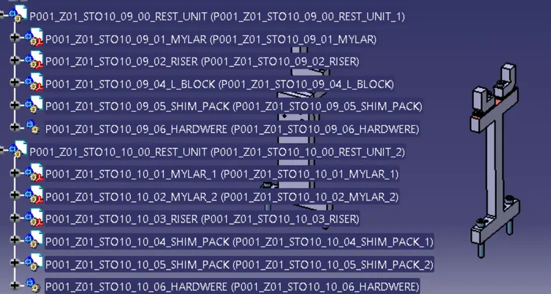
Rest unit is unit designed to support car panel using mylar / NC block / Rest component is related only, no upper clamp or force applied there. It is the simplest unit to design because it has fewer parts to design & the purpose is only resting of the car panel.
Power Clamp Unit:
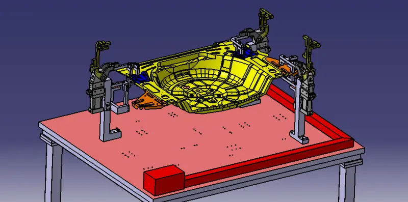
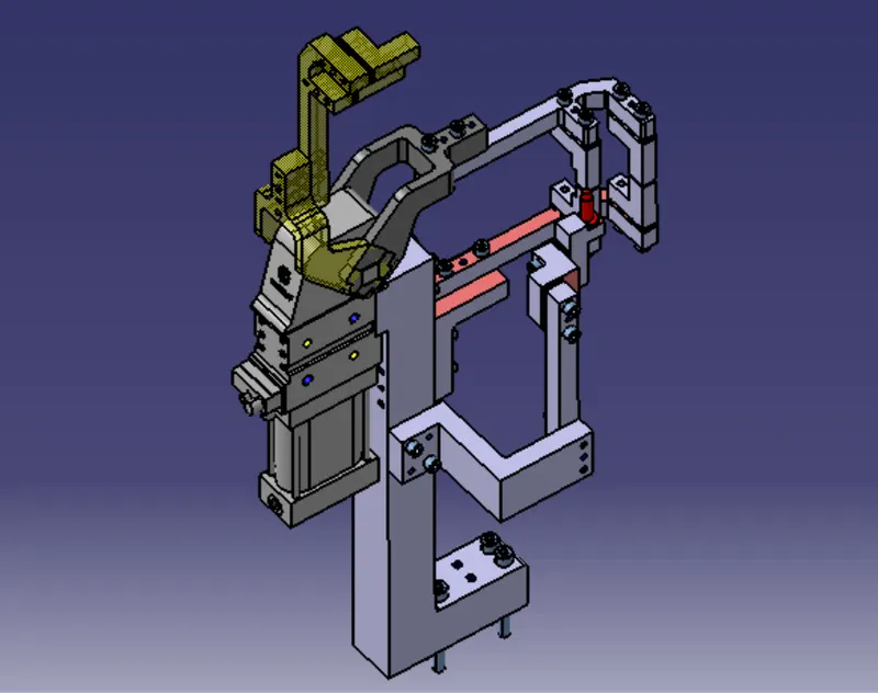
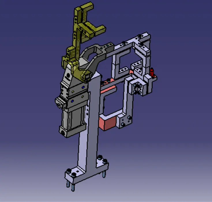
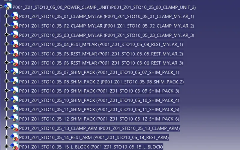
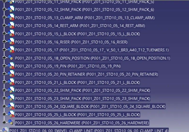
A clamp unit is a unit designed to clamp / hold the car panel with NC blocks/ mylars / Rest by using a pneumatic cylinder. Clamp arm, finger, rest / backup, L- block, shims, riser, pneumatic cylinder are the typical are parts of clamp unit. Clamping forces should be considered while designed clamp unit. Usually clamp open position is 90 degree. Fingers are attached to clamp Mylar. In clamp unit shim to one side is more enough because it will retractable transition motion in upward direction & downward direction only . There is another type of clamp unit known as swivel type. There is pivot pin around which clamp arm rotate.
PIN UNIT:
A pin unit is a unit designed to locate the car panel using pins. There are two types of pin units. They are
- Fixed Pin unit.
- Retractable Pin unit.
- Single rod
- dual rod
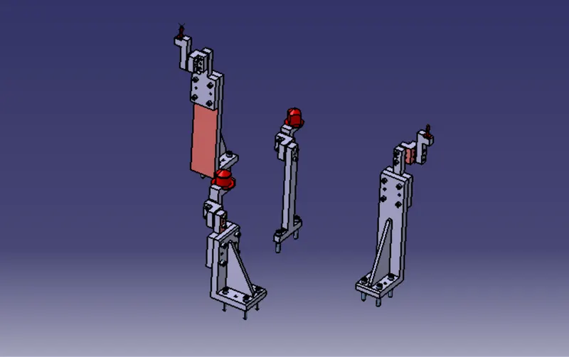
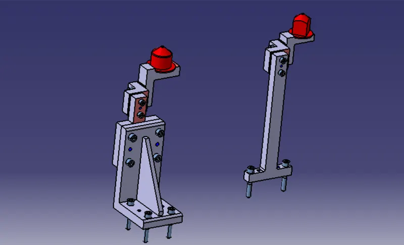
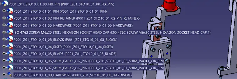
The below are the different parts of a fixed pin unit ;
- Pin
- Pin retainer
- Shims/Spacers
- Block
- Blade/ Adaptor Plate
- Riser
- Cylinder
SWIVEL CLAMP UNIT:
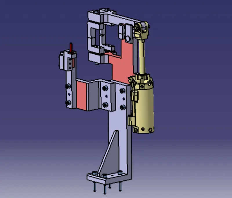
A clamp unit is a unit designed to clamp / Hold the car panel with NC blocks / Mylars / rest by using a pneumatic cylinder. Clamp arm, finger, rest/ backup, L-Block, Shims , riser, pneumatic, cylinders are the typical parts of clamp are the parts of clamp unit. Clamping force should be consider while designed clamp unit. Usually clamp open position is 90 degree. Fingers are upward to clamp arm.
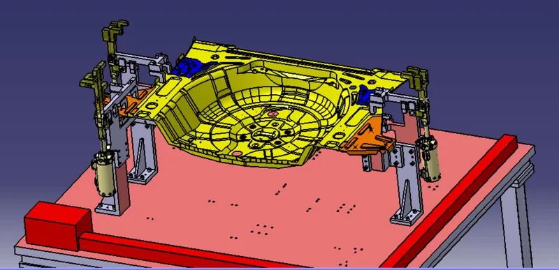
PIN CLAMP UNIT :
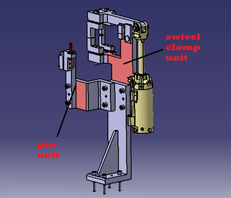
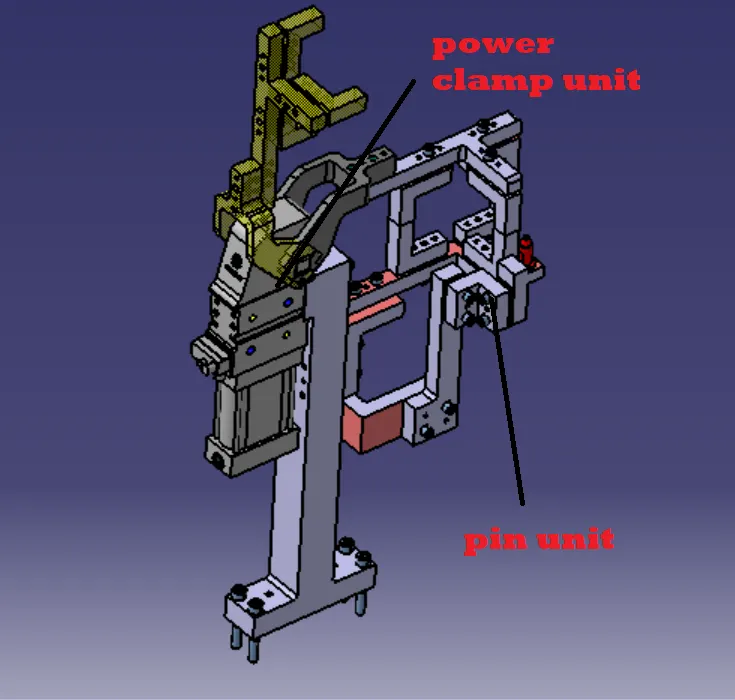
Structuring of tree:-
Structuring a design tree implies process where all the assemblies & parts are named in specific manner. Diff errant customers have different set of standards like how to structure a design tree? So, they will give standard template based on that design tree structured, which helps us to identify specific part of assembly. It specifies the Project number, station number, unit number; part number of each component so that it is easy to identify the parts.It is an important process which helps us to identify a specific part or assembly as to which project, tool or unit, it belongs to.
This helps us to avoid error during design study, manufacturing, assembly, Inspection etc.If parts or assemblies are not named properly or the design tree is not structured properly, it will create confusion to understand & create major possibilities of making an error.Naming of a fixture, a unit or a part gives the information as to which project or zone or assembly they do belong.It can help us to identify quantity of items of same type or diff errant types that are being used in assembly for e.g. bolt. It actually tells you how many bolts are particularly required in that assembly or unit
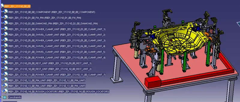
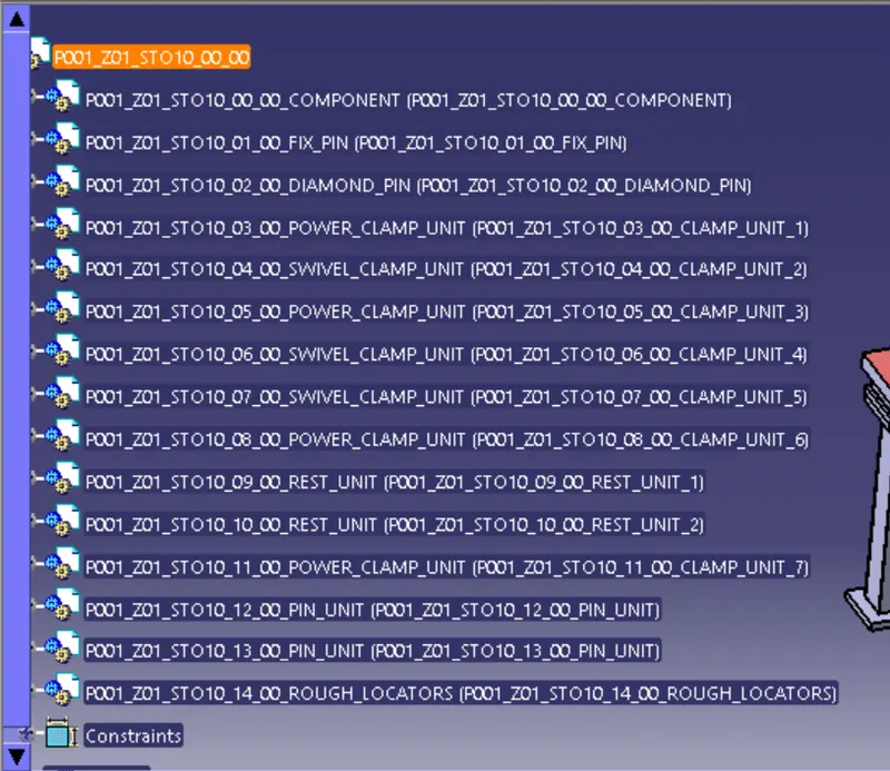
IMAGES OF ALL THE UNITS USED IN THE ASSEMBLY AFTER 3D FINISHING:
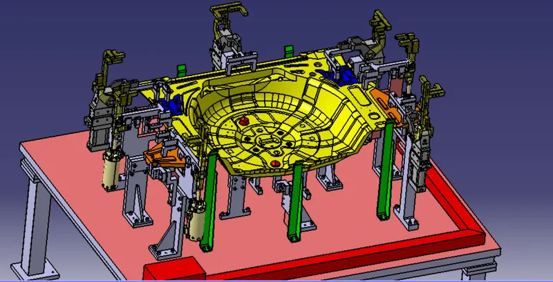
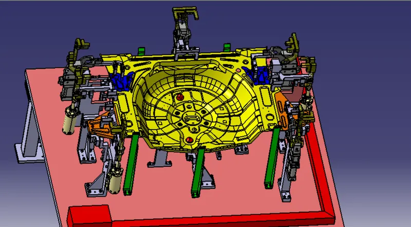
- The Rough Locator unit was created with proper design methodologies.
- The 3D finishing process was performed with atmost perfection.
- Necessary images and part files were attached.