Week 8:- 3D Finishing Challenge 2
Aim/ Introduction :
- Perform 3D finish for all units of assembly design. Creat rough locators for assembly.
- Create Rough locators for the Assembly design
Theory :
3D Finish
3D finish is a process where the design is being completely finish & to be ready for final simulation & 2D detailling .
Following points are taken into consideration while finishing the design.
- Hole concentricity & hole sizes
All parts holes concentricity & holes sizes are cheked for easy assembly while finishing the parts.
- Machinig area
The machining area in every part is defined & the machining area is heghlighted by using orange colour.
- Nominality
All units dimensions are maintained nominal to facilitate easy assembly of the unit.
- Holes colouring Standard
Color code standard used in the 3D finishing.
- Vivolet - Simple hole
- Yellow - Threaded Hole
- Cream - Machined area
- Cyan - Dowel pin Hole.
- Fasteners Implementation
Fasteners are implemented in all unit as per requirement & load on the part.
- Avoiding clash between different part
Proper maintained the gap between parts to avoid the clash
- Mylar Splitting as per panel profile
Mylar splitting are confirmed while finishing the design.
- Proper renaming of parts/assemblies as per standard-proper renaming of parts & assemblies are done while finishing the design hence we can identify each & every part easily with a unique identification.
1. Renaming & Structuring of the design tree:
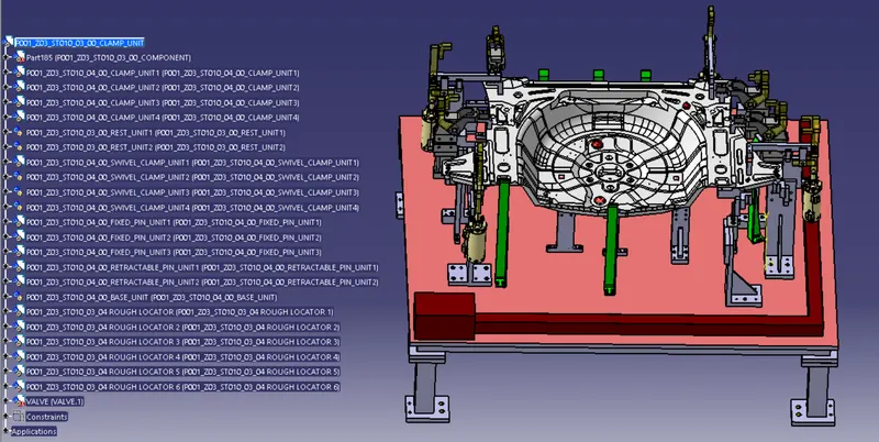
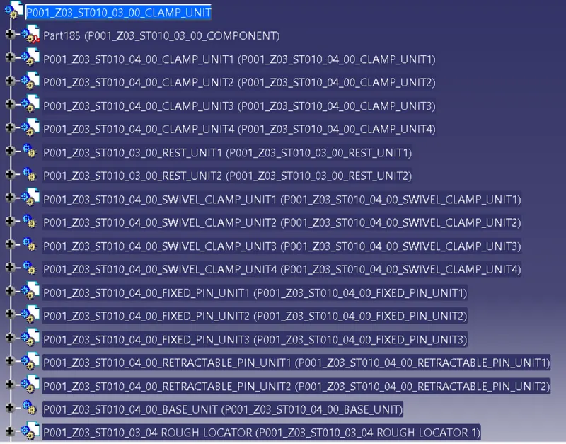
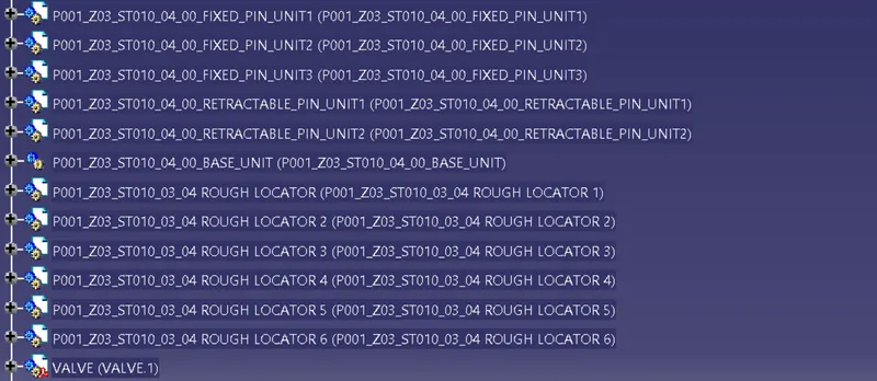
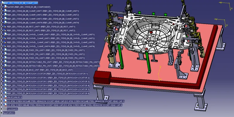
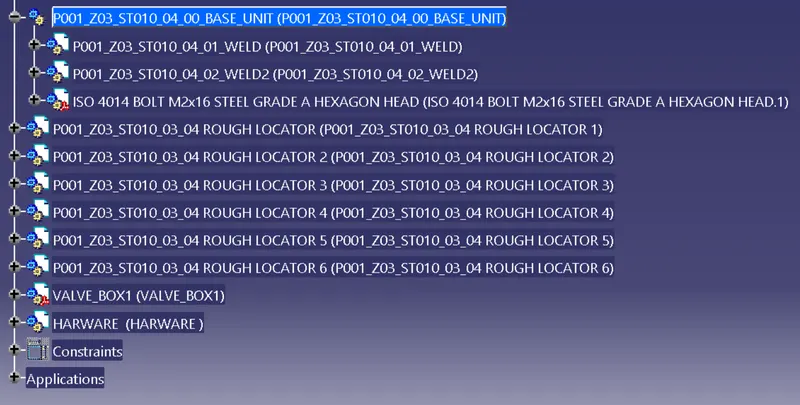
- Renaming of the design tree is done. & structuring design tree in way that its simple to identify the units . Some units use multiple time those are easy to identify by its name.
2. Base unit :
A base unit is the unit designed to mount all the other units of the tool, also other parts necessary for a tool like pneumatic valve box, trunking cable path will also be mounted on to a base unit.
Below are the some parts of a base unit in general.
- Trunking channel
- base plate
- Valve box
- Measuring hole cover
- Eye bolt.
- Pedestal.
- Weld Bars.
- Floor plate.
Typical parts of a base unit:
Base unit :
Base plate is a machined plate of 20 to 40mm thickness made of steel and aluminium on to which the holes are drilled to mount the individuals units like clamp units . Pin units etc of a tool.
There are three key benifits to a base plate;
- They can help to quickly and accurately tram in fixtures and vises.
- They can hold large, complicated, or odd- Shaped parts.
- They protect the cast iron machine table.
Pedestal:
A pedestal is a part which connects the base plate to the floor plate. A pedestal is a standard part in general, & in some cases it can be a welded frame integrated with the base plate.
A standard pedestal can be of different heights and different sizes.
Depending on the size of the base plate, the number of pedestal varies for load distrubution.
A pedestal are of different types with different inclinations.
Trunking Channel:
Trunking channel is a standard part which will accommodate all the pneumatic & electrical hoses and wires for the units. The trunking channel includes all the prssure inlet cables going to the pneumatic parts of the fixture & protect them from damaging while operation is in process.
Valve Box:
Valve box is a standard part which will contain all the valves for the pneumatic units. The valve box is the box which includes different solenoid valves. The pneumatic fixture work on air pressure provided to it. So the arrangement of air pressure inlet & outlet is done within this valve box . The trunking channel includes all the pressure inlet cables going to the parts of the fixture and protects them from damaging while operation in process.
Eye Bolt :
An eye bolt is a bolt with a loop at end one. They are used to firmly attach a securing eye to a structure, so that ropes or cables may them the be tied to it.
Machinary eye bolts are fully threaded and may have a collar, Making them suitalbele for use with angular loads up to 45 degree. Eye bolts without a shoulder should not be used for angular loads. Heavy forged eye bolts with a continuous eye may be forged with an integral shoulder. allowing their use for heav off-axis loads.
- Renaming parts & Structuring design Tree:
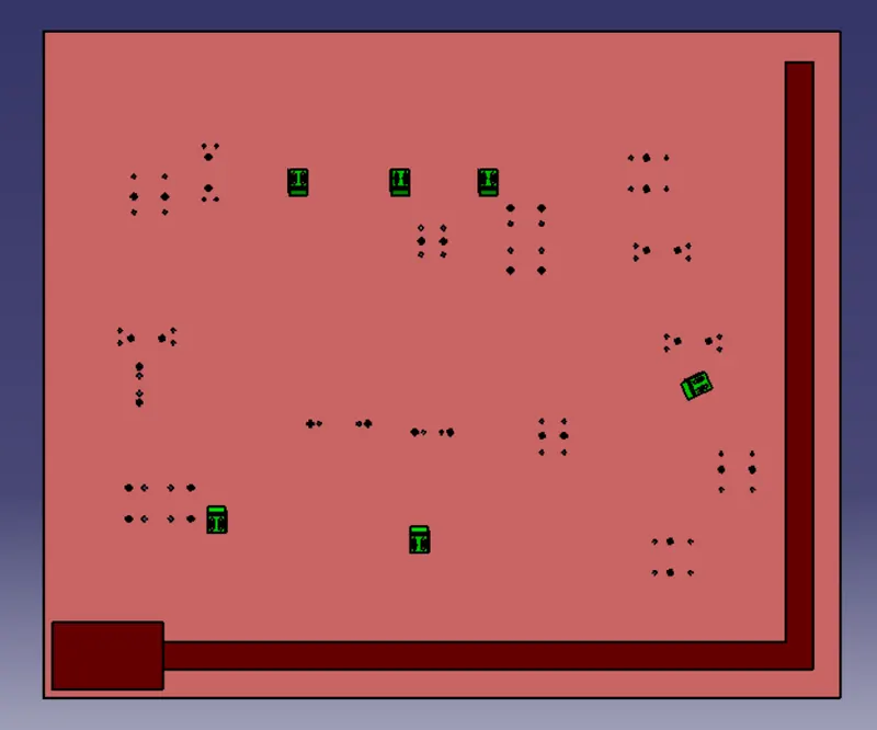
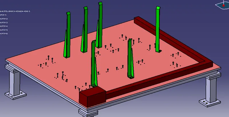
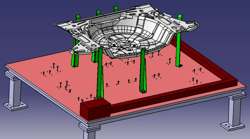
- Positioning Of Rough Locators on the base plate:
- Hole Made to nominal base plate.
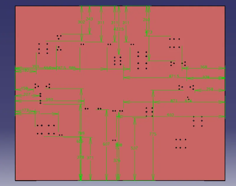
Rest Unit :
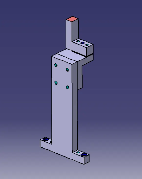
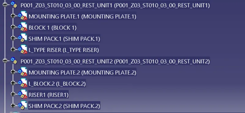
Rest unit is unit designed to support car panel using mylar / NC block / Rest component is reletaed only, no upper clamp or force applied there. It is the simplest unit to design because it has fewer parts to design & the purpose is only resting of the car panel.
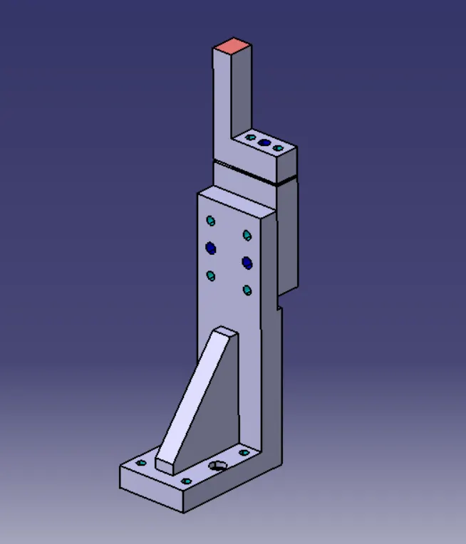
Power Clamp Unit :
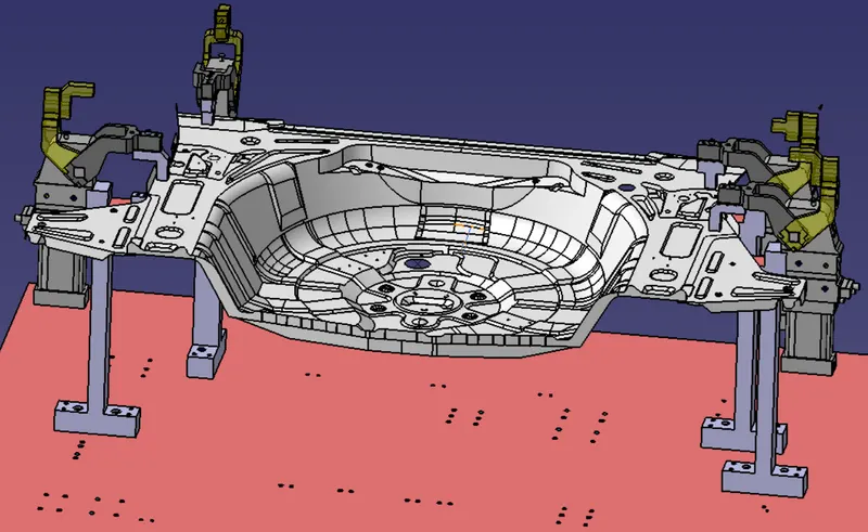
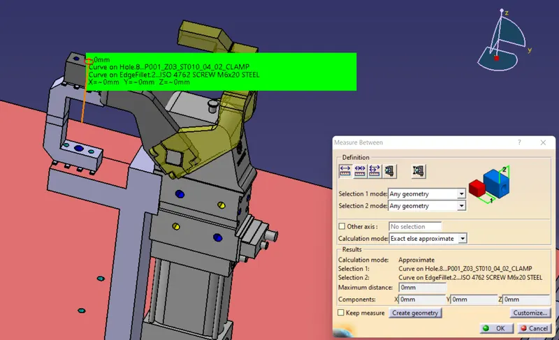
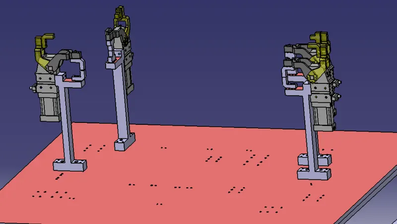
A clamp unit is a unit designed to clamp / hold the car panel with NC blocks/ mylars / Rest by using a pneumatic cylinder . Clamp arm , finger, rest / backup, L- block, shims, riser, pneumatic cylinder are the typical are parts of clamp unit. Clampimg froces should be considerd while designed clamp unit. Usually clamp open position is 90 degree. Fingers are attached to clamp Mylar. In clamp unit shim to one side is more enough because it will retractbale transiation motion in upwared direction & downward direction only . There is another type of clamp unit known as swivel type. There is pivot pin around which clamp arm rotate.
PIN UNIT :
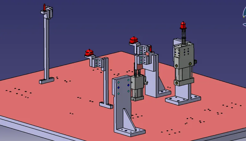
A pin unit is a unit designed to locate the car panel using pins. There are two types of pin units. They are
- Fixed Pin unit.
- Retractable Pin unit.
- Single rod
- dual rod
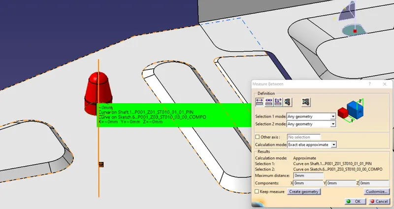
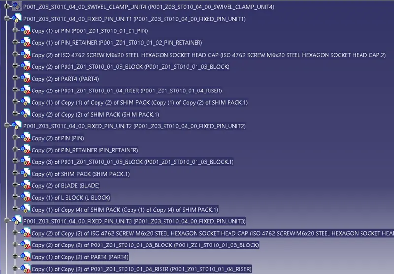
The below are the different parts of a fixed pin unit ;
- Pin
- Pin retainer
- Shims/Spacers
- Block
- Blade/ Adaptor Plate
- Riser
- Cylinder
SWIVEL CLAMP UNIT:
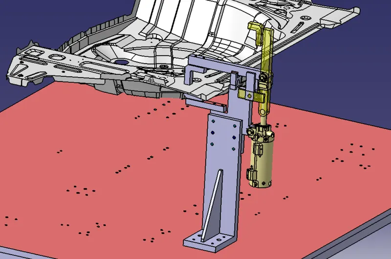
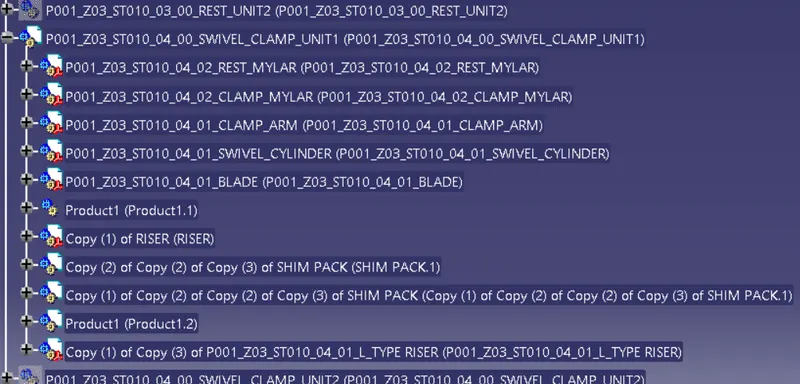
A clamp unit is a unit designed to clamp / Hold the car panel with NC blocks / Mylars / rest by using a pneumatic cylinder. Clamp arm , finger, rest/ backup, L-Block, Shims , riser, pneumatic,cylinders are the typical parts of clamp are the parts of clamp unit. Clamping force should be considerdwhile designed clamp unit. Usually clamp open position is 90 degree . Fingers are upward to clamp arm .
PIN CLAMP UNIT :
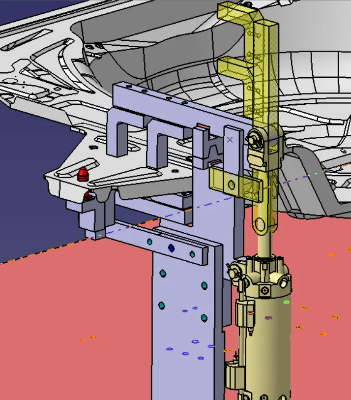
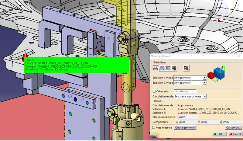
RETRACTABLE PIN UNIT :
A retractable pin unit is a unit designed to locate the car panel using pins, But the entire packge parts will be mounted on the retractable pneumatic cylinder.
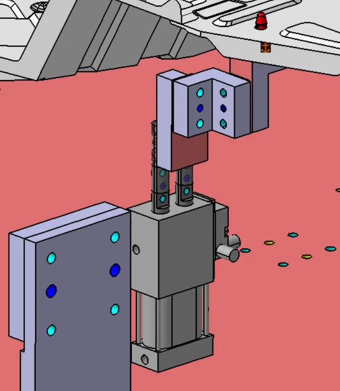
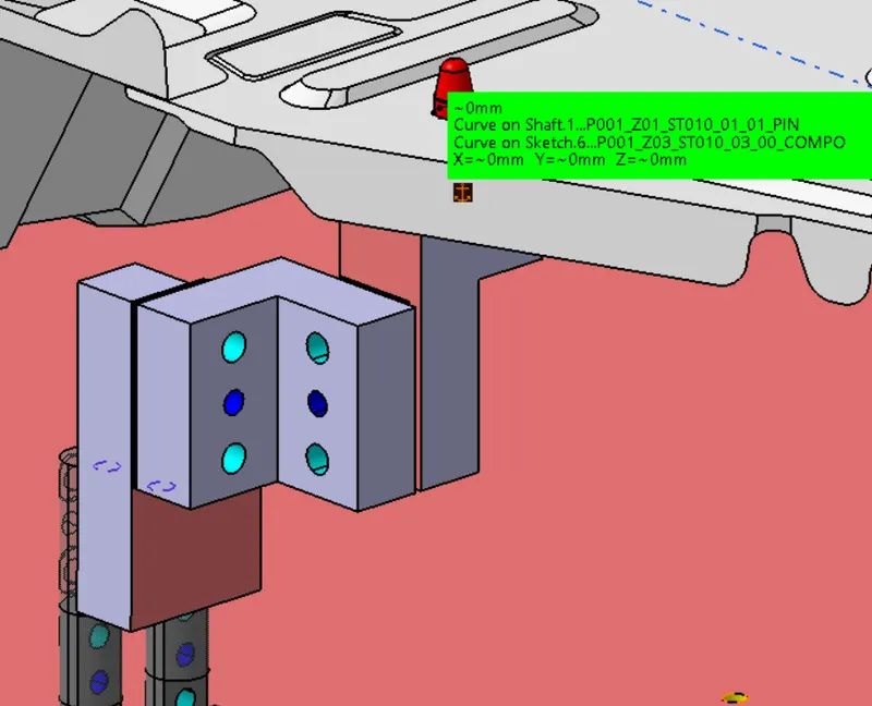
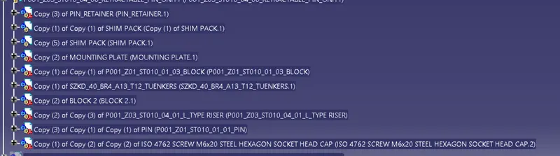
IMAGES OF ALL THE UNITS USED IN THE ASSEMBLY AFTER 3D FINISHING:
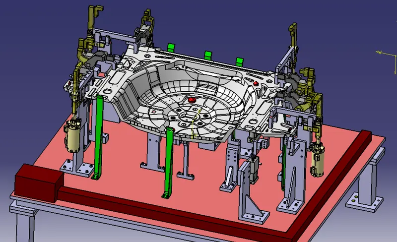
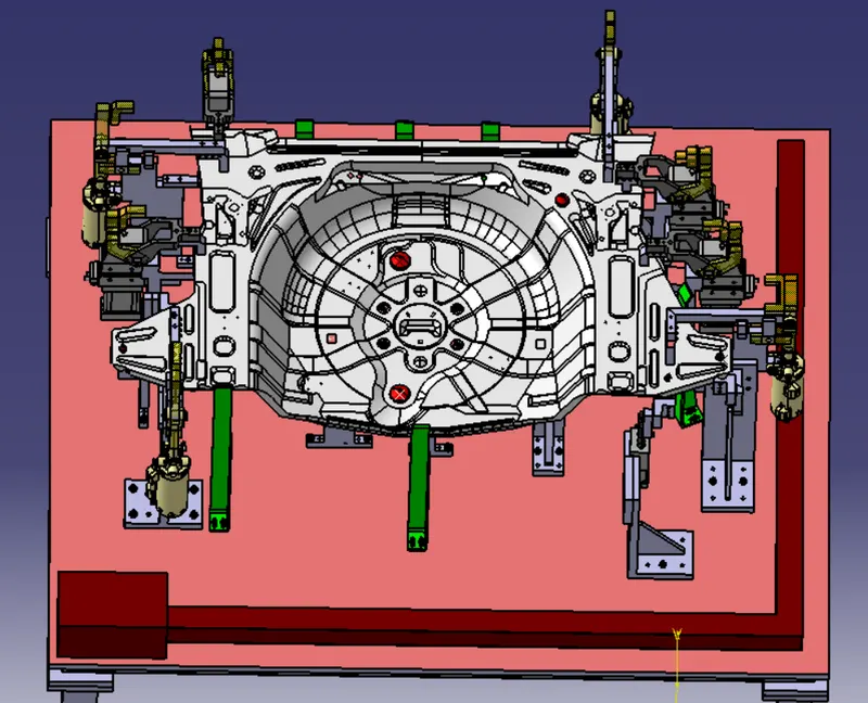
CONCLUSION :
Hence, 3D finishinged is performed on the designed Assembly of fixture & Rough locators were designed for the given panel.